background image

AT-HDR-SW-52ED

40

Device Operation

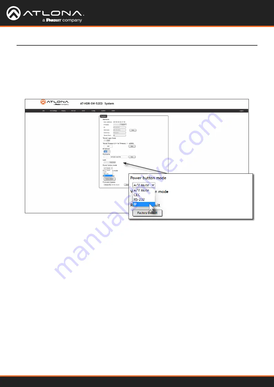
Optional IP Front Panel Button Control

To send power and volume commands to the display, using the 

POWER

 and 

VOLUME

 buttons on the front panel, 

following the instructions below:  

1.  Click 

System

 in the menu bar.

2.  Click the 

Power button mode

 drop-down list and select 

IP

.

3.  To control volume on the display, click the 

Volume button mode

 drop-down list and select 

IP

.

Summary of Contents for Atlona AT-HDR-SW-52ED

Page 1: ...AtlonaManuals Switchers AT HDR SW 52ED Five Input HDMI Switcher 4K HDR with Mirrored Outputs...

Page 2: ...AT HDR SW 52ED 2 Version Release Date Notes 1 Jul 2023 Initial release Version Information...

Page 3: ...ose CA 95134 United States Office 1 408 962 0515 Sales and Customer Service Hours Monday Friday 6 00 a m 4 30 p m PST https atlona com International Headquarters Atlona International AG To distrasse 1...

Page 4: ...the following two conditions 1 this device may not cause harmful interference and 2 this device must accept any interference received including interference that may cause undesired operation This equ...

Page 5: ...7 Switching Modes 18 Mirrored Mode 18 Matrix Mode 19 Auto Switching 21 Enabling Disabling Auto Switching 21 Scaler Pass Through 22 Notes on Scaling 23 Audio Management 24 HDMI HDBaseT Audio Muting 24...

Page 6: ...nel 54 Resetting to Factory Default Settings 55 Configuration and Management Interfaces 56 Web Server 56 Register page 56 Login page 57 Info page 58 A V Settings page 59 Display page 61 RS 232 page 66...

Page 7: ...amic range HDR formats Part of the comprehensive family of Atlona 4K HDR integration products it features five HDMI inputs and matrixed or mirrored HDMI and HDBaseT outputs The HDBaseT output transmit...

Page 8: ...A solid blue indicator represents the active input being used 2 VOLUME Displays the output audio level Refer to LED Indicators page 15 for more information 3 POWER Press this button to toggle between...

Page 9: ...T Connect a category cable from this port to a the HDBaseT IN port of a compatible receiver unit 6 FW Connect a USB to mini USB cable to this port from a computer for firmware updates 7 IR IN OUT Conn...

Page 10: ...e Local Area Network LAN This step will be required in order to access the built in web server 5 Connect the included 5 pin captive screw connector to the 5 pin AUDIO port Refer to Analog Audio Output...

Page 11: ...u d i o AT GAIN 60 AT HDR EX 100CEA RX Ceiling Speakers A u d i o Gen eric SPEAKER SYSTEMS SPEAKER SYSTEMS Gen eric SPEAKER SYSTEMS SPEAKER SYSTEMS Gen eric SPEAKER SYSTEMS SPEAKER SYSTEMS Gen eric SP...

Page 12: ...ilable will automatically assign an IP address to the unit If the AT HDR SW 52ED is unable to detect a DHCP server within 15 seconds then the unit will use a self assigned IP address within the range...

Page 13: ...tation for more information Setting the IP Address Using Commands The IP mode of the AT HDR SW 52ED can also be set using the built in web server In order to access the web server the IP address of th...

Page 14: ...computer then do the following 1 Click Start Settings Control Panel Network and Sharing Center 2 Click Change adapter settings 3 Right click on the adapter that is used to establish a wired connection...

Page 15: ...io is free of distortion Solid red Audio signals which exceed 0 dBFS are represented in this range Audio clipping occurs at this level If clipping is heard reduce the output gain of the source device...

Page 16: ...ore the built in web server can be accessed a username and password must be created 3 Enter the desired username in the Username field In the example above the username admin is used 4 Enter the desir...

Page 17: ...owser and enter the IP address of the AT HDR SW 52ED in the address bar 2 Enter the correct username and password in the respective fields 3 Click the Submit button Logging in after Registration 4 The...

Page 18: ...utput signal will be displayed on both the HDMI OUT and HDBaseT OUT port The active input will be identified on the front panel HDMI LED input indicators and will be displayed as a solid green LED Aut...

Page 19: ...eration This mode allows the AT HDR SW 52ED to independently switch between any input to any output Auto Switching is disabled in Matrix Mode Audio on the L R and S PDIF OUT ports will always follow H...

Page 20: ...the Matrix Mode HDMI Source drop down list and select the input to be routed to the HDMI OUT port 5 Click the Matrix Mode HDBaseT Source drop down list and select the input to be routed to the HDBaseT...

Page 21: ...he previously active input is no longer available then the AT HDR SW 52ED will fallback to any available input The AT HDR SW 52ED provides Auto Switching capability which is enabled by default This fe...

Page 22: ...es on Scaling page 23 for more information 1 Log in to the web server 2 Click A V Settings in the menu bar 3 Click the HDMI Output 1 and or HDBT Output 2 toggle switch to the ON position 4 The followi...

Page 23: ...lows Input Output 4K 24 Hz 1080p 24 Hz 4K 30 Hz 1080p 30 Hz 4K 60 Hz 4 2 0 1080p 60 Hz YUV RGB 4 4 4 HDR Dolby Vision HLG formats cannot be downscaled to 1080p The internal scaler will be bypassed if...

Page 24: ...DBaseT OUT port click the associated toggle switch to the OFF position To re enable the audio for that output set the toggle switch to the ON position The AT HDR SW 52ED provides volume control and in...

Page 25: ...not support audio only free run mode output The included 5 pin captive screw block can be wired to support balanced audio using XLR connectors or unbalanced audio using RCA connectors The GND signal...

Page 26: ...osition 5 Under Analog Audio Output Volume click and drag the slider to adjust the audio output level The current output volume in decibels will be displayed in the Analog Output field next to the sli...

Page 27: ...o Muting 1 Log in to the web server 2 Click A V Settings in the menu bar 3 Locate the Audio section 4 Click the S PDIF Output toggle switch to the OFF position To re enable the audio on the S PDIF OUT...

Page 28: ...in the menu bar 3 Locate the Audio section 4 Click the S PDIF Output from RX Optical Input toggle switch to the OFF position To re enable the audio on the optical port of the receiver set the toggle...

Page 29: ...in to the web server 2 Click A V Settings in the menu bar 3 Locate the HDCP section 4 Click the toggle switch next to the desired input In this example clicking the Input 1 toggle switch and setting...

Page 30: ...FACT ORY RESET Control System AT HDR SW 52ED HDM I 1 HDM I 2 HDM I 3 HDM I 4 HDM I 5 VOLU ME AT H DR S W 5 2ED POW ER INPU T 3 Click RS 232 in the menu bar 4 Under the RS232 Console section select the...

Page 31: ...12V SIG GND 12V SIG GND 1 COMP ONEN T HDMI 1 2 3 4 5 6 SERIA L 1 IR OUT SERIA L 2 L R DIGIT AL COAX OUT AUDIO OUT AUDIO IN ETHE RNET 2 3 4 VIDEO OUT 48V DC FACT ORY RESET AT HDR SW 52ED AT HDR EX 100C...

Page 32: ...2 HD MI 3 HD MI 4 HD MI 5 VO LU ME AT HDR SW 52 ED PO WE R INP UT AT HDR EX 100CEA RX POW ER LIN K AT HD R E X 1 00C EA RX FW G N D S P W R A T H D R S W 5 2 E D C o n t r o l S y s t e m P W R G N D...

Page 33: ...100CEA RX PO WE R LIN K AT HD R E X 1 00C EA RX FW AT HDR SW 52ED HD MI 1 HD MI 2 HD MI 3 HD MI 4 HD MI 5 VO LU ME AT HDR SW 52ED PO WE R INP UT 3 Connect the IR emitter to the receiver and place the...

Page 34: ...ers will identify CEC with their own brand name Refer to the table below Manufacturer CEC Designation Hitachi HDMI CEC LG SIMPLINK Philips EasyLink Samsung AnyNet Sony BRAVIA Sync Toshiba CE Link REGZ...

Page 35: ...fault control method If the display does not respond check the following Verify that CEC is enabled on the display device Verify the integrity of the HDMI cable Try connecting a different cable betwee...

Page 36: ...e commands to the display using the POWER and VOLUME buttons on the front panel following the instructions below 1 Click System in the menu bar 2 Click the Power button mode drop down list and select...

Page 37: ...n 2 Log in to the web server 3 Click A V Settings in the menu bar 4 Set the Switching Mode to Mirrored Display control is not supported under Matrix Mode 5 Click RS 232 in the menu bar 6 Set the RS 23...

Page 38: ...232 Front Panel Button Control To send power and volume commands to the display using the POWER and VOLUME buttons on the front panel following the instructions below 1 Click System in the menu bar 2...

Page 39: ...Mode 5 Click Display in the menu bar 6 Under System Settings click the Control Type drop down list and select IP 7 Under TCP IP Settings of Controlled Device click the IP Mode drop down list and sele...

Page 40: ...me commands to the display using the POWER and VOLUME buttons on the front panel following the instructions below 1 Click System in the menu bar 2 Click the Power button mode drop down list and select...

Page 41: ...1 Scroll down to the bottom of the page and locate the RS 232 IP commands section 2 Click the Manufacturer drop down list and select the manufacturer of the device that is being controlled In the exam...

Page 42: ...splay Refer to the User Manual for the display device for more information If the command must be repeated continue with the following steps Otherwise skip to Step 5 a Under Repeat Command click the S...

Page 43: ...rrectly In most cases a CR carriage return should be specified In the example above x0D is the hexadecimal value for a carriage return HEX Command Strings ASCII Command Strings a Enter the ASCII comma...

Page 44: ...Storing EDID Data By default the AT HDR SW 52ED will read the EDID from the display device The term downstream is used to describe any device that receives a signal from another device For example if...

Page 45: ...ts IMPORTANT If problems are encountered when using an EDID preset it is recommended that the input be set to Connected Display Not all displays will support all video and audio formats in a given EDI...

Page 46: ...ect an HDMI cable from either HDMI OUT port on the AT HDR SW 52ED to the HDMI input on the display containing the EDID to be stored 2 Log in to the web server 3 Click EDID in the menu bar 4 Locate the...

Page 47: ...EDID Since the display is connected to the HDMI OUT 1 port on the AT HDR SW 52ED Output 1 is selected from the MEM 1 drop down list 6 Click the Save button next to the drop down list for the memory l...

Page 48: ...ppears as an available EDID preset for each available input on the AT HDR SW 52ED Device Operation Saved EDID NOTE Once an EDID is written to a memory location it can be overwritten with a different E...

Page 49: ...lick the Old Password field and enter the current password 5 Enter the new username in the New Username field 6 Enter the new password in the New Password field 7 Retype the new password in the Confir...

Page 50: ...e assigned an IP address on the network and no further network configuration is required However if the AT HDR SW 52ED is unable to detect a DHCP server within 15 seconds then the unit will use a self...

Page 51: ...spectively 7 Click the Save button to commit changes Changes will take effect immediately Changing the Telnet Port Typically the Telnet service is assigned to TCP port 23 This is the default setting f...

Page 52: ...4 Click Save to commit changes Telnet Login Mode Telnet Timeout When a Telnet session is requested the AT HDR SW 52ED provides the option to prompt for user credentials or bypass authentication befor...

Page 53: ...dback from the commands or any system changes Read queries such as the IPCFG and Type commands are not announced and will only return information to the requester 4 Click Save to commit changes 1 Log...

Page 54: ...This may be desirable if for example the AT HDR SW 52ED is installed in a rack environment By default the front panel buttons are unlocked 1 Log in to the web server 2 Click System in the menu bar 3...

Page 55: ...will be set to DHCP mode 1 Log in to the web server 2 Click System in the menu bar 3 Click the Factory Default button 4 The following message will be displayed at the top of the screen Click OK to co...

Page 56: ...a built in web server Atlona recommends that the web server be used to set up the AT HDR SW 52ED as it provides intuitive management of all features Refer to Logging in after Registration page 17 for...

Page 57: ...AT HDR SW 52ED 57 Configuration and Management Interfaces Login page Username Enter the username in this field Password Enter the password in this field Submit Click this button to log in...

Page 58: ...Valens firmware for the HDBaseT chip On Time d h m s Displays the amount of time elapsed since the unit was powered System Info Video Info Displays signal information for both the HDMI output Output...

Page 59: ...Switching Mode Click this drop down list to manually select the switching mode Refer to Switching Modes page 18 for more information Setting Description Input 1 Sets HDMI IN 1 as the active input Inpu...

Page 60: ...or disable audio output on the L R port S PDIF Output Click this toggle switch enable or disable audio output on the S PDIF OUT port S PDIF Output from RX Optical Input Click this toggle switch enabl...

Page 61: ...ol If this is not possible then other control methods will need to be considered in order to control displays using Atlona products CEC System Settings Display Auto Power On Select Active Video Presen...

Page 62: ...setting is 10 Seconds Control Type Click this drop down list to set the control protocol for the connected display Click this drop down to select the control type Available settings are RS 232 IP and...

Page 63: ...eat Command Times If the Status toggle switch is set to ENABLED then this drop down list will be available Click this drop down list to select the number of times to send the command Available values...

Page 64: ...en set to Non Login the login credential fields Username and Password will be hidden The default setting is Non Login IP Address Enter the IP address of the device in this field Port Enter the port nu...

Page 65: ...before an acknowledge message is received from the display Refer to the User Manual for the display device for more information The default setting is ENABLED Repeat Command Times If the Status toggl...

Page 66: ...of data The following options are available None Odd or Even Stop bit Sets the stop bit Stop bits are sent at the end of each character allowing the client to detect the end of a character stream The...

Page 67: ...o select the desired EDID to be used for each input The following EDID presets are available When selecting an EDID make sure that the display sink device is capable of supporting the resolution timin...

Page 68: ...ssword in this field New Username Enter the new username in this field New Password Enter the new password in this field Confirm New Password Verify the new password by retyping it in this field Save...

Page 69: ...rt of a Telnet session OFF No username and password is required for Telnet sessions IP Enter the IP address of the AT HDR SW 52ED in this field This field will only be available if IP Mode is set to S...

Page 70: ...POWER button will send the commands over Ethernet using either the LAN port Setting Description LOCK Locks the front panel buttons UNLOCK Unlocks the front panel button allowing them to be functional...

Page 71: ...CEC protocol The output volume of the AUDIO ports on the AT HDR SW 52ED is unaffected Volume commands are sent over both the HDBaseT OUT and HDMI OUT ports RS 232 VOLUME buttons will send RS 232 comma...

Page 72: ...the Valens chip on the transmitter RX Version The version of the Valens chip on the receiver TMDS Clock Displays the pixel clock speed If no source is connected then this field will display as None C...

Page 73: ...e from the computer containing the firmware to the same network where the AT HDR SW 52ED is connected 2 Log in to the web server and go to the System page page 69 Appendix 3 Click the Choose File butt...

Page 74: ...op the firmware file to the virtual drive During the firmware update procedure the POWER button will flash more rapidly 6 After the file has been copied disconnect the USB cable from both the computer...

Page 75: ...ews on the sides of the unit to attach the mounting brackets 1 Attach the included small rack ear to one side of the AT HDR SW 52ED using the included screws 2 Attach the included longer rack ear to t...

Page 76: ...N NET AUDIO DEVICE ID GAINTM H D M I 1 H D M I 2 H D M I 3 H D M I 4 H D M I 5 V O L U M E A T H D R S W 5 2 P O W E R IN P U T H D M I 1 H D M I 2 H D M I 3 H D M I 4 H D M I 5 V O L U M E A T H D R...

Page 77: ...he circular holes on each mounting plate If using a drywall surface a 6 drywall screw is recommended Mounting screws are not included Appendix NOTE The unit can also be mounted under a flat surface su...

Page 78: ...bsampling 4 4 4 4 2 2 4 2 0 Color Depth 8 bit 10 bit 12 bit HDR HDR10 Hybrid Log Gamma HLG and Dolby Vision 60 Hz Audio HDMI Pass Through Formats LPCM 2 0 LPCM 5 1 LPCM 7 1 Dolby Digital Dolby Digital...

Page 79: ...renheit Celsius Operating Temperature 32 to 122 0 to 50 Storage Temperature 4 to 140 20 to 60 Operating Humidity RH 20 to 90 non condensing RS 232 Port 1 x 3 pin captive screw Use Unit and external de...

Page 80: ...TAA Yes Warranty Device 3 years Weight Pounds Kilograms Device 1 44 3 15 Dimensions H x W x D Inches Millimeters Unit 1 34 x 8 19 x 4 41 34 x 208 x 112 Power Supply AT PS 48083 C 1 42 x 1 81 x 4 41 36...

Page 81: ...US International atlona com 408 962 0515 41 43 508 4321 35295 R1...

Reviews: