


- 3 –
ZVP-PC-0154-00-R1
NOTE: FOR FINE ABRASIIVE, IT IS NECESSARY
TO SLIGHTLY CLOSE THE PUSHER LINE CHOKE
BALL VALVE TO INCREASE DIFFERENTIAL
PRESSURE TO ASSIST ABRASIVES FLOW
THROUGH THE ABRASIVE METERING VALVE.
! WARNING! – EXCCESSIVE THROTTLING OF
THE CHOKE VALVE WILL CAUSE HIGH WEAR
ON ABRASIVE METERING VALVE.
3.1.13
To stop blasting, the blast operator indicates to
the pot tender, who closes the main supply ball
valve (Figure A. No.2), and then quickly opens
the air exhaust valve (Figure A. No.1), which
depressurizes the blast pot and drops the pop
up valve.
3.2
Shutdown procedure
3.2.1
Close the main supply ball valve located on the
blast pot.
3.2.2
Opens the air exhaust ball valve (figure A. no.1),
which depressurizes the blast pot to release the
pop up valve.
Figure
B.
3.2.3
Shut down the air compressor.
3.2.4
Cover the blast machine with the lid (where
supplied) and coil up and store the blast hose
and to prevent accidental damage.
4.0 MAINTENANCE
! WARNING! – THE COMPRESSED AIR
SOURCE MUST BE ISOLATED BEFORE
PERFORMING ANY MAINTENANCE WORK.
FAILURE TO DO SO MAY CAUSE SERIOUS
INJURY OR DEATH.
4.1 On a daily basis
4.1.1
If fitted, drain any water/moisture from the
moisture separator by opening the drain valve
located on the bottom of the water trap bowl.
Unscrew the retaining ring and remove the
water trap bowl. Check the filter element for
blockages and replace as required. Re-fit the
bowl and locking ring, and close the bowl drain
valve.
NOTE: IT IS ALWAYS GOOD TO ENSURE THE
INCOMING PRESSURIZED AIR IS EQUIPPED
WITH A DRYER SYSTEM TO ENSURE THE
INLET AIR IS DRY.
4.1.2
Inspect the blast hose for wear by feeling along
its full length for soft spots, which indicate wear,
and replace the hose as necessary.
4.1.3
Check all blast hose couplings are secure and
that all safety-locking pins are correctly in place.
4.1.4
Remove the safety locking pins and disconnect
the couplings by twisting the coupling counter
clockwise. Inspect the coupling gaskets for wear
and correct seating. Replace the gaskets as
required. Reconnect the coupling by engaging
the lugs with the pot coupling and twisting the
hose coupling until fully engaged, and then re-
fit the safety locking pins.
4.2 On a weekly basis
4.2.1
Remove the blast nozzle from the nozzle holder
by unscrewing the nozzle in a counter clockwise
direction, and inspect it for wear. Replace the
nozzle if when the internal diameter is worn by
1.5mm (1/16”) from its original size, or if the
liner is chipped or cracked.
4.2.2
Check the condition of the nozzle washer and
replace as required, then re-fit/replace the blast
nozzle by screwing it clockwise into the nozzle
holder until it is fully sealed against the nozzle
washer.
4.2.3
Check the condition of the nozzle holder, and
inspect for any cracks or signs of damage.
Replace if required as detailed in section 2.1.2.
4.3 On a monthly basis
4.3.1
Inspect the pop up valve located in the top of
the blast pot for wear in the form of cracks or
grooves (section 6.1.1. item1). If replacement is
required, remove the pot shell inspection cover
located on the side of the blast pot. Using a
suitable pipe wrench, unscrew the vertical pipe
section which houses the pop up valve, and
remove both the pipe section and pop up valve
through the inspection opening. Installation of
the new pop up valve is a reversal of the
removal procedure. Ensure that the pop up valve
is positioned directly below the top opening for
correct sealing.
Figure C.
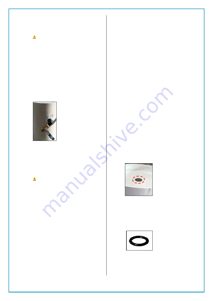
4.3.2
Check and inspect the pop up valve seating ring
for wear (section 6.1.1. item2). If replacement is
necessary, use a large screw driver or similar
tool to pry the seating ring out of the seat.
When re -fitting the new seating ring, ensure
that it is correctly seated within the seating ring
housing.
Figure D.
4.3.3
Inspect the blast pot exhaust muffler and
exhaust line (if fitted) for wear or blockages,
replace the worn or blocked muffler and
exhaust line as necessary.


