


- 2 –
ZVP-PC-0154-00-R1
2.1.4
Securely attach a suitably sized compressed air
line to the blast pot main air supply ball valve,
ensuring that the main air supply ball valve is in
the closed position. It is preferable for the
compressed air line to be at least one size larger
than the piping size on the blast pot. Ensure
that all coupling safety locking pins and/or
locks are correctly fitted to the compressed air
connection. Panblast recommends the use of
correctly sized safety whip check cables at all
compressed air line and blast hose connections.
2.1.5
Check that the nozzle holder rubber washer is
correctly installed then screw the blast nozzle
fully into the nozzle holder, ensuring that it
forms a seal against the nozzle holder rubber
washer.
2.1.6
The blast pot is now ready for operation
3.0
OPERATING INSTRUCTIONS
3.1 Blasting operating instructions
Blast pot operations
NOTE: CHECK WITH YOUR LOCAL
AUTHORITIES TO DETEMINE IF IT IS
PERMISSIBLE TO OPERATE A MANUALLY
CONTROLLED BLAST POT IN THE LOCAL AREA.
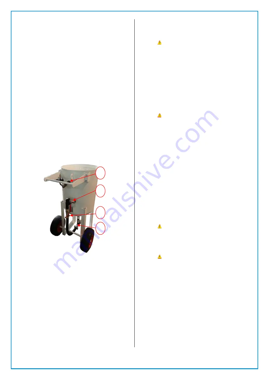
BP600-3
Figure
A.
3.1.1
Ensure that the blast pot & compressed air
supply has been set up as detailed in section
2.0 of this manual.
3.1.2
Check that the main air supply ball valve (Figure
A. No.2) of the blast pot piping is fully closed
3.1.3
Check that the choke line ball valve is fully open
(Figure A. No.3)
3.1.4
Check that the blast pot exhaust ball valve is
fully closed (Figure A. No.1)
3.1.5
Fully close the abrasive metering ball valve
(Figure A. No.4) located on the bottom of the
blast pot by turning the control handle to a right
angle position.
3.1.6
Load the abrasive media into the blast pot by
pouring it in through the pop up valve opening
located on top of the blast pot. The blast pot
screen (where supplied) should be used to
prevent coarse debris and oversize particles
from entering the blast pot.
! WARNING! –DO NOT OVERFILL THE BLAST
POT. THE ABRASIVE LEVEL SHOULD REMAIN
BELOW THE BOTTOM OF THE POP UP VALVE
TO PREVENT PREMATURE WEAR TO THE
EXHAUST VALVE ASSEMBLY.
3.1.7
Check that all hose connections, fittings, safety
locking pins etc. are all secure and in the proper
location.
3.1.8
Start the air compressor, and allow the
compressor to reach the desired operating
pressure. Do not set the blast pressure below
345Kpa (50psi) as the blast system may not
operate correctly (this is to ensure that the pop
up valve will operate).
! WARNING! – DO NOT EXCEED THE
MAXIMUM OPERATING PRESSURE OF THE
BLAST POT AT ANY TIME AS THIS COULD
RESULT IN SERIOUS INJURY OR DEATH.
NOTE: THE SYSTEM IS NOW READY TO
OPERATE AND THE BLAST POT WILL
PRESSURIZE IF THE MAIN SUPPLY BALL VALVE
IS TURNED ON.
THE OPERATOR SHOULD WEAR APPROVED
SUPPLIED AIR RESPIRATORY EQUIPMENT (SAR)
BEFORE ACTIVATING THE BLASTING MACHINE.
3.1.9
Pick up the blast hose at the blast nozzle end,
and direct the blast nozzle at the surface/part
to be blasted.
3.1.10
When ready, the blast operator indicates to the
pot tender, who then closes the exhaust ball
valve (Figure A. No.1) and then opens the main
air supply ball valve (Figure A. No.2) which
pressurizes the blast pot and lifts the pop up
valve. Compressed air will only exit at the blast
nozzle.
! WARNING! - DO NOT OPEN THE MAIN AIR
SUPPLY BALL VALVE IF THE BLAST NOZZLE IS
NOT FIRMLY HELD BY THE OPERATOR.
UNSECURED BLAST HOSE WITH COMPRESSED
AIR FLOW WILL WHIP AND MAY CAUSE
SERIOUS INJURY OR DEATH.
! WARNING! – DO NOT EXCEED THE
MAXIMUM OPERATING PRESSURE OF THE
BLAST POT.
3.1.11
Once the blast pot is pressurized, check the
piping for air leaks. If leaks are found, close the
main supply air ball valve and open the exhaust
ball value. Shut down the compressor before
rectifying any air leaks.
3.1.12
If no leaks are found, slowly rotate the abrasive
metering ball valve handle (Figure A. No.4) from
the 90 degree closed position, until the desired
abrasive flow level is achieved. The optimum
abrasive flow level will vary depending on actual
operating conditions and the desired end result,
but as a general rule, the abrasive should
appear in the air stream as a fine mist. Once the
desired abrasive flow rate has been achieved,
the system is now set for ongoing blasting
operations.
1
2
3
4


