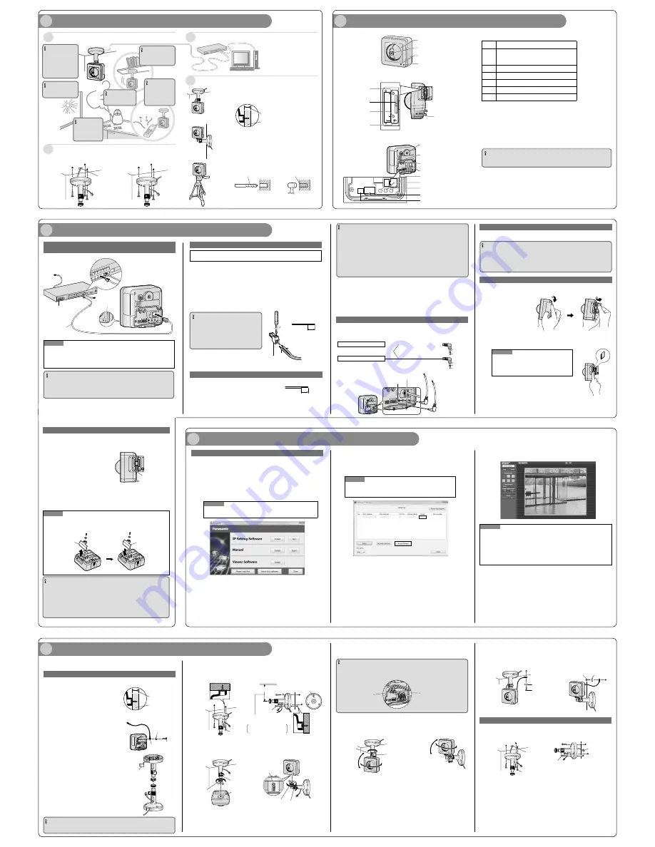
MIC POWER
To the power supply
LAN cable
PoE indicator
LINK indicator
To the hub or
the router
Indicator
When connecting the camera using PoE (Power over
Ethernet)
When connecting the camera using 12 V DC power supply
Caution:
FOR UL LISTED MODEL(S), ONLY CONNECT 12 V DC CLASS 2 POWER SUPPLY.
1
Loosen the screw of the power cord plug (accessory).
2
Connect the cable of the 12 V DC power supply* to the power cord plug.
Strip 3 mm to 7 mm {1/8 inches to 9/32 inches} from the end of the wire, and twist the
stripped part of the wire sufficiently to avoid short circuit.
Specification of cable (wire): 16 AWG - 24 AWG, Single core, twisted
Check whether the stripped part of the wire is not exposed and is securely connected.
3
Tighten the screw of the power cord plug.
4
Connect the power cord plug to the 12 V DC power supply terminal on the rear of the cam-
era.
IMPORTANT
Be sure to use the power cord plug provided
with this product.
Be sure to fully insert the power cord plug
into the 12 V DC power supply terminal.
Otherwise, it may damage the camera or
cause malfunction.
¢
Installing the camera on the ceiling or wall
Make sure the flexible stand is firmly mounted on a beam of wood (25 mm [1 inch] and
greater) etc. When there is no beam, apply a board on the other side of the ceiling or wall
to make sure the camera does not drop.
When mounting on a mortar or concrete surface
Prepare anchors for 4 mm (3/16 inch) diameter screws for mounting.
Mortar ceilings or walls break easily when drilling. Be careful of pieces
of mortar which may become loose and fall.
1. Place the flexible stand on the ceiling or wall where you plan to mount the
flexible stand and mark the points where you are going to make holes.
2. Make holes with an electric drill. Insert anchors (locally procured)
into the holes and push them inside the holes with a hammer.
3. Mount the flexible stand using the screws.
Drill for concrete (in case of tile,
use a drill for tile)
Perform waterproof treatment
(caulking)
Determining the mounting position
Determining the length of the cable
Determining how to wire the cable
Determining how to mount the camera
It is necessary to make a hole in the ceiling or wall to pass the cables
through. Make a hole 25 mm {31/32"} in diameter.
¢
Tripod Mount
It is also possible to mount the camera on a standard tripod stand (locally
procured).
Confirm the distance from the camera's
installation position to the computer and
then prepare the necessary length of LAN
cable (locally procured).
Hole for cables
ø 25 mm (ø 1 inch)
IMPORTANT
Do not connect 2 wires or more directly to a terminal. When it is necessary to connect 2
or more wires, use a splitter.
Input and output of the external I/O terminal 2 and 3 can be switched by configuring the
setting. The default of EXT I/O terminal 2 is "ALARM IN 2" and of EXT I/O terminal 3 is
"ALARM IN 3". It is possible to determine whether or not to receive input from EXT I/O
terminal 2 and 3 (ALARM IN2, 3) by selecting "Off", "Alarm input", "Alarm output" or "AUX
output" for "Terminal alarm 2" or "Terminal alarm 3" on the [Alarm] tab on the "Alarm setup"
page. Refer to the Operating Instructions (included in the CD-ROM) for further information.
The default of EXT I/O terminals is "Off". When "Off" is selected, it is possible to connect
external devices as well as the input setting.
When using the EXT I/O terminals as the output terminals, ensure they do not cause
signal collision with external signals.
<Ratings>
ALARM IN1, ALARM IN2, ALARM IN3
Input specification : No-voltage make contact input (4 V - 5 V DC, internally pulled up)
OFF
: Open or 4 V - 5 V DC
ON
: Make contact with GND (required drive current: 1 mA or more)
ALARM OUT, AUX OUT
Output specification : Open collector output (maximum applied voltage: 20 V DC)
Open
: 4 V - 5 V DC by internal pull-up
Close
: Output voltage 1 V DC or less (maximum drive current: 50 mA)
Microphone/line input connector · Audio output terminal
You can connect an external microphone and external speaker to the camera to use the Listen and Talk
features, respectively. The microphone cable should be no longer than 7 m (23 feet). If you use an external
microphone, excessive cable length or a poor quality cable can cause degradation in audio quality.
Monitor out connector for adjustment
Connect a monaural mini plug (ø3.5 mm) (only for checking if images are displayed on the monitor).
Recommended plug: L type
IMPORTANT
The monitor out connector for adjustment is provided only for checking the adjustment of
the angular field of view on the video monitor when installing the camera or when servic-
ing. It is not provided for recording/monitoring use.
Black bands may appear at the top and bottom or right and left of the screen. (That does
not affect the adjustment because the angular field of view is not changed.)
Insert a SD memory card
1
Open the cover on the side of the camera.
2
Insert the SD memory card with the label facing the rear of the camera and the pins
facing the front of the camera. Gently push the card with your finger until it clicks.
Note
If the camera’s indicator turns red, remove the SD
memory card and confirm that the card is not write-
protected. If the indicator is still red, the card must be
formatted before it can be used.
3
Close the cover.
IMPORTANT
Do not mount this product on
a plaster board or a wooden
section because they are too
weak. If this product is
unavoidably mounted on such
a section, the section
shall be sufficiently reinforced.
IMPORTANT
Do not install this by
products that
generates a strong
radio wave or a strong
magnetic field.
IMPORTANT
Do not install on
locations subject to
humidity and oil
smoke.
IMPORTANT
Do not install near the
strong light source.
IMPORTANT
Do not install near
any heat sources.
IMPORTANT
Do not install this on
locations subject to
vibrations.
Note
If the indicator does not turn green, see “Troubleshooting” in the Operating Instructions
on the provided CD-ROM.
Refer to the operating instructions of the product in use about the operations of the PoE
device.
IMPORTANT
Use a 4-pair UTP/STP cable.
Make sure that the PoE device in use is compliant with IEEE802.3af standard.
For information on recommended PoE devices, refer to our website at
(http://panasonic.net/pss/security/support/ info.html).
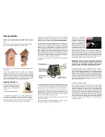
1
Check the installing place
<Front view>
<Side and bottom view>
<Rear view>
Lens cover
Lens
Microphone
Indicator
INITIAL SET button
SD memory card slot
FUNCTION button
(lit when recording)
Stand/tripod mounting hole
Stand mounting hole
12 V DC power supply terminal/
Monitor out connector for adjustment/
External I/O terminals cable hook
LAN port [10BASE-T/100BASE-TX]
Audio output terminal/Microphone/
line input connector cable hook
Microphone/line input connector
[MIC/LINE IN]
Audio output terminal [AUDIO OUT]
Monitor out connector for adjustment
[MONITOR OUT]
External I/O terminals [EXT I/O]
12 V DC power supply terminal [POWER]
External I/O terminals
Pin
Function
6
DC power output
Power output voltage 10.5 V
~
13 V
Power output current 100 mA
5
GND
4
GND
3
EXT I/O terminal 3 (ALARM IN 3/ AUX OUT)
2
EXT I/O terminal 2 (ALARM IN 2/ ALARM OUT)
1
EXT I/O terminal 1 (ALARM IN 1)
About the [INITIAL SET] button
After turning off the power of the camera, turn on the power of the camera while holding down this
button, and wait for around 5 seconds or more without releasing this button. Wait around 3 minute
after releasing the button. The camera will start up and the settings including the network settings
will be initialized. Before initializing the settings, it is recommended to write down the settings in
advance. The initialization will be complete when the live indicator stops blinking orange and lights
off. Note that the preset position settings and the CRT key (SSL encryption key) used for the
HTTPS protocol will not be initialized.
IMPORTANT
Do not turn off the power of the camera during the process of initialization. Otherwise,
it may fail to initialize and may cause malfunction.
About the [RESTART] button
When the camera is on, you can also restart the camera by pressing the RESTART button. Press
and hold the RESTART button for about one second with a pointed object. Restarting is completed
when the camera's pan/tilt performs its initial movement.
an external microphone/ line input
an external powered speaker
(ø 3.5 mm mini plug)
(ø 3.5 mm stereo mini plug)
cable ø2 ±0.3
(Output impedance 560 Ω line level)
(Plug-in power 3.3 ±0.5 V)
GND
GND
unconnected
signal
signal
3
Connections
2
Major operating controls
− +
+
−
Strip range
Approx. 3 mm - 7 mm
{1/8 inches - 9/32 inches}
Power cable plug
(accessory)
MIC
POWER
INITIAL
SET
REST
AR
T
FUNCTION
RESTART button
EXT I/O
POWER
- +
12V = IN
6 5 4 3 2 1
10BASE-T/
100BASE-TX
Beam of wood
At least 25 mm (1 inch)
External I/O terminals
Connect external devices to the EXT I/O terminal.
When connecting an external device, remove 9 mm - 10 mm
{11/32 inches - 13/32 inches} of the outer jacket of the cable
and twist the cable core to prevent the short circuit first.
Specification of cable (wire): 22 AWG - 28 AWG
Single core, twisted
Strip range
Approx. 9 mm - 10 mm
{11/32 inches - 13/32 inches}
For audio output terminal
For microphone/ line input terminal
To microphone
To speaker input terminal
Adjust the camera to a suitable position/direction while confirming the images actually displayed
on the computer screen.
Wiring without making a hole for a cable in the ceiling or wall
1
Place the flexible stand (accessory) on
the ceiling or wall, and determine the
mounting position of the stand.
Make sure the flexible stand is firmly mounted on a
beam of wood (25 mm [1 inch] and greater) etc. When
there is no beam, apply a board on the other side of the
ceiling or wall to make sure the camera does not drop.
2
Secure the safety wire (accessory) to
the camera using screw A (accessory)
and washer S (accessory).
3
Remove the tab on the flexible stand.
4
Pass the cables through the notch.
When there are many cables to pass through the
notch, pass through the larger cables first.
IMPORTANT
If the cables cannot be passed through the notch, wrap the cables to the stand shaft using
tape (locally procured) or other materials.
5
Mounting the Camera
Configuring the camera so that it can be accessed from a PC
If you are using firewall software on your PC, the Setup Program may not be able to find any cam-
eras on your network. Configure the setting of the camera after temporarily invalidating the firewall
software.
1
Insert the provided CD-ROM into the CD-ROM drive of your PC
The License Agreement will be displayed. Read the Agreement and choose "I
accept the term in the license agree-ment", and click [OK].
The launcher window will be displayed.
If the launcher window is not displayed, double click the "CDLauncher.exe" file on
the CD-ROM.
Note
Refer to "About the CD-ROM" in the Operating Instructions on the provided
CD-ROM for further information about CDLauncher.
Remove a SD memory card
1
Close the slide cover on the side of the camera.
2
Press the FUNCTION button.
When the FUNCTION button is pressed,
recording stops and the green light turns
off. Confirm that the FUNCTION button
green light has turned off before
proceeding to step 3.
3
Push the card slightly to eject it, then remove the card.
4
Close the cover.
Note
To suit the area in which you will install the camera, you can attach the provided SD Card
Cover (Hard type), in order to help prevent SD card theft.
Not all forms of theft can be prevented.
IMPORTANT
Make sure that SD memory card recording has stopped and that the card is not being accessed
before removing the card. (The FUNCTION button will light while images are being recorded to the
card.) We recommend pressing the FUNCTION button to stop SD memory card recording before
ejecting the card.
If the SD memory card is removed while it is being recorded to or accessed, the card
may become unreadable and may need to be formatted (i.e., erased) again before
use.
FUNCTION button
5
Mount the flexible stand firmly to the ceiling or wall with screw B
(accessory).
When mounting the flexible stand to the wall, position the flexible stand so that the "
p
"
marker is facing upward.
6
Attach the camera by screwing the threaded mount into the stand
mounting hole.
Beam of wood
At least 25 mm
(1 inch)
7
Pass the cables through the connector cover, and then connect all
necessary cables (AC adaptor, LAN, audio/video, etc.). Refer to
"Connections".
IMPORTANT
When installing the camera, hook the cord of the AC adaptor (locally procured) and the
cables for the external speaker/external sensor/mic/video, etc. around the hooks when mak-
ing connections.
8
Adjust the camera position and tighten the flexible stand grip and
the tightening screw firmly.
The fixing position of the tightening screw can be adjusted according to
the direction the camera is facing and its angle.
9
Adjust the length of the safety wire when it is taut, and secure it to
the ceiling or wall using screw B (accessory) and washer L
(accessory).
Attach the safety wire in a position so that if the camera were to become detached, it
would not fall on nearby people.
Wiring through a hole made in the ceiling or wall
Make a hole for cables in the ceiling or wall. Secure the safety wire to the camera and pass the
cables through the notch. Then follow steps 2, 4 to 9.
It is not necessary to remove the tab on the flexible stand.
Screw A
(accessory)
Washer S
(accessory)
Safety wire
(accessory)
At least 165 mm
Screw B
Screw B
(accessory)
¢
Ceiling
¢
Wall
¢
Ceiling
¢
Wall
Grip
Stand mounting hole
Threaded mount
Indicator
Stand/tripod
mounting hole
Grip
* It is possible to attach the stand to the
stand mounting hole, the rear of the
camera.
Audio output terminal/
Microphone/line input
connector cable hook
12 V DC power
supply terminal/
Monitor out connector
for adjustment/
External I/O terminals
cable hook
Screw B
Screw B
¢
Ceiling
¢
Wall
Washer L (accessory)
Washer L (accessory)
Screw B
Screw B
¢
Ceiling
¢
Wall
Hole for cables
ø 25 mm (ø 1 inch)
Hole for cables
ø 25 mm (ø 1 inch)
4
Configure the settings of the camera
SD Card Cover
(Hard type)
SD Card Cover
(Soft type)
the tab on the
flexible stand
¢
Ceiling
¢
Wall
Grip
Tightening screw
Tightening screw
Grip
p
p
Keep a distance of 165 mm
{0.54 feet} or more from a ceiling
Otherwise the camera
cannot be mounted
properly.
2
Click the [Run] button next to [IP Setting Software]
"Panasonic IP Setting Software" page will be displayed. Click the [Network Settings] button
after selecting the MAC address/IP address of the camera to be configured.
3
Select the camera you want to configure, and click [Access Camera].
Note
When cameras are displayed in [IP Setting Software] screen, click the cam-
era with same MAC address as the MAC address printed on the camera
that you want to configure.
Threaded mount
4
When the [Access Camera] button is clicked, live images of the
selected camera will be displayed.
Note
When no image is displayed on the “Live” page, refer to “Troubleshooting” in the Operating
Instructions on the provided CD-ROM.
It is possible to enhance the network security by encrypting the access to cameras using
the HTTPS function. Refer to “Access the camera using the HTTPS protocol” in the
Operating instructions on the provided CD-ROM.
Click the [Setup] button on the “Live” page, the user authentication window will be dis-
played. Enter the default user name and password as follows, and log in.
User name: admin
Password: 12345