background image

22

Step 5

Press the [UP], [DOWN], [RIGHT], and [LEFT] buttons to determine the lower right position of the zone to be set and press the [SET] 
button. 

 An asterisk “*” will be displayed after the number and the zone setting will be saved. 

Step 6

When “ON (2)” is selected for “PRIVACY ZONE”, the mosaic level may be adjusted. The mosaic level may be set through “ZONE 
LEVEL”. (Range: 1 to 4) 

Note:

  •  To delete a zone, select the zone number and press the [SET] button after moving the cursor to “DEL”. 
  •  To change the settings of a zone, select the zone number and repeat from step 3. 

12. Image stabilizer setting [STABILIZER]

Whether or not to enable the image stabilizer is determined. 
This function is effective for the case that the camera is installed at a place with slight shaking. 

ON:

 Enables the image stabilizer. 

OFF

 (default)

:

 Disables the image stabilizer. 

Important:

  •  When “ON” is selected for the image stabilizer, the view angle becomes narrower and the resolution becomes lower. When “ON” 

is selected for the image stabilizer, check the view angle and resolution at camera installation. 

  •  The image stabilizer function may not work for the following subjects or conditions.
    • Dark subject 
    • Less contrasty subject (e.g. white wall) 
    • Subject shaking at excessive speed  
    • Large amplitude image shaking

13. Electronic zoom setting [EL-ZOOM] 

Whether or not to use the electronic zoom is determined. 

ON:

 Uses the electronic zoom. 

OFF

 (default)

:

 Does not use the electronic zoom. 

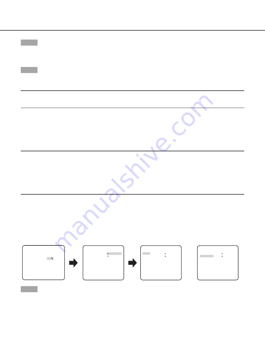
When “ON” is selected, the zoom factor and the panning/tilting settings can be configured. 
Follow the procedure below.

      **EL-ZOOM**

      **EL-ZOOM**

**EL-ZOOM**

PUSH SET

PUSH SET

ZOOM

PAN/TILT

PUSH SET

PUSH SET

ZOOM

PAN/TILT

PUSH SET

PUSH SET

ZOOM

PAN/TILT

U ZOOM D

U TILT D/L PAN R

“SYSTEM SETUP” screen

“EL-ZOOM” screen 

Pan/tilt setting screen

Zoom setting screen

 RET TOP END

 RET TOP END

 RET TOP END


OFF

    **SYSTEM SETUP** 

SYNC          INT

PRIVACY ZONE

STABILIZER    OFF

EL-ZOOM       ON

UPSIDE-DOWN   OFF
 

 -     +

LDC           I......  0

 RET TOP END

Step 1

Move the cursor to “EL-ZOOM” and select “ON” and press the [SET] button. 

 The “EL-ZOOM” screen appears. 

Summary of Contents for WV-CW324LE Series

Page 1: ...for future use The model number is abbreviated in some descriptions in this manual Operating Instructions Color CCTV Camera Model No WV CW324LE Series WV CF314LE Series WV CW324LE WV CF314LE This manu...

Page 2: ...corporated in the United States and or other countries About notations The following notations are used when describing the functions limited for specific models The functions without the notations ar...

Page 3: ...ise reduction function setting DNR 16 8 Black and white mode setting D N IR 16 9 VMD setting VMD 18 Setting of motion detection 19 Setting of scene change detection 20 Camera system setting SYSTEM SET...

Page 4: ...ra system such as synchronization alarm input output terminal and privacy zone SYNC Only INT method can be used PRIVACY ZONE Hides undesired portions in the camera shooting area STABILIZER Decides whe...

Page 5: ...ECIAL LANGUAGE Screenshot 3 The selected setup screen in the setup menu appears on the screen Note If the top screen of the setup menu is called up with the operation buttons the setup mode is always...

Page 6: ...SI RET TOP END RESET CAMERA SETUP screen CAMERA SETUP SCENE1 ALC ELC ALC SHUTTER OFF AGC ON LOW SENS UP OFF WHITE BAL ATW1 DNR HIGH AUTO2 VMD RET TOP END D N IR OFF SPECIAL SETUP screen SPECIAL SETUP...

Page 7: ...SI RET TOP END RESET CAMERA SETUP screen CAMERA SETUP SCENE1 ALC ELC ALC SHUTTER OFF AGC ON LOW SENS UP OFF WHITE BAL ATW1 DNR HIGH AUTO2 VMD RET TOP END D N IR OFF SPECIAL SETUP screen SPECIAL SETUP...

Page 8: ...ABCDEFGHIJKLM NOPQRSTUVWXYZ SPACE POSI RET TOP END RESET CAMERA SETUP screen CAMERA SETUP SCENE1 ALC ELC ELC SHUTTER AGC ON LOW SENS UP OFF WHITE BAL ATW1 DNR HIGH AUTO2 VMD RET TOP END D N IR OFF SP...

Page 9: ...END RESET SYSTEM SETUP PRIVACY ZONE OFF SYNC INT STABILIZER OFF EL ZOOM OFF UPSIDE DOWN OFF LDC I 0 RET TOP END BACK FOCUS SETUP ABF PUSH SET MANUAL ADJ C L B W FIX RET TOP END SPECIAL SETUP screen LA...

Page 10: ...STUVWXYZ SPACE POSI RET TOP END RESET SYSTEM SETUP SYNC INT PRIVACY ZONE OFF STABILIZER OFF EL ZOOM OFF UPSIDE DOWN OFF LDC I 160 RET TOP END SPECIAL SETUP screen LANGUAGE SETUP screen LANGUAGE SETUP...

Page 11: ...racter The entered characters are displayed in the editing area Character entry To revise a character move the arrow in the editing area to a wrong character with use of the RIGHT or LEFT button and e...

Page 12: ...r left button to select SCENE2 The screen changes and displays SCENE2 Step 3 To configure the settings of SCENE2 using the settings of SCENE1 press the SET button after moving the cursor to COPY SCENE...

Page 13: ...t the ON or OFF ON Activates the BLC function OFF default Deactivates the BLC function Step 3 Move the cursor to ABS and select from the following options ABS Auto Black Stretch Technology The latest...

Page 14: ...324L CW314L CW304L CF314L CF304L Control the quantity of light with ELC appears and the shutter function cannot be activated 4 Gain control setting AGC Select a gain control setting from the following...

Page 15: ...ance control mode This adjustment is suitable for a location where a light source is stable The adjustment of the color temperature ranges from 2000 K to 10000 K When AWC is selected the white balance...

Page 16: ...he direction the color becomes lighter Step 3 Move the cursor to AREA and press the SET button to enter AREA setting screen The area to detect white area of white balance can be set on the area settin...

Page 17: ...length of the light source shall be 800 nm or longer When AUTO1 is selected to obtain color images a sufficient level of illuminance approx 30 lx or more is required When AUTO2 is selected to obtain c...

Page 18: ...n of motion or scene change with the camera can be announced by issuing an alarm signal Important The following circumstances may result in detection failure or false detection Use the camera after ad...

Page 19: ...SK SET I 20 In the masked area no alarm will be issued even if a moving object is detected The masked area is set in the same way as the masked area setting in Light quantity control method selection...

Page 20: ...once a continuously moving object is detected within the specified time Setting of scene change detection This function detects a change in the subject state that occurs by covering the camera with a...

Page 21: ...ormally Follow the procedure below to set the privacy zone Note The privacy zone function is disabled at initializing the unit i e right after turning on the power ZONE NUMBER 1 8 PUSH SET POSITION UP...

Page 22: ...narrower and the resolution becomes lower When ON is selected for the image stabilizer check the view angle and resolution at camera installation The image stabilizer function may not work for the fo...

Page 23: ...and left buttons to determine the position of the area to be set and press the SET button The position can be changed in the range of zoom factor set in the zoom setting screen 14 Upside down setting...

Page 24: ...e back focus function will not adjust automatically when switching between color and black and white images Important The auto back focus function is used for back focus adjustment at installation and...

Page 25: ...terference fringes may be observed when shooting a subject with fine pattern such as a carpet or a curtain In such a case move the indicator in the direction to reduce moire 21 Pedestal level adjustme...

Page 26: ...left buttons to select the number with which the target pixel compensation point is registered and press the SET button The registered pixel compensation point is cleared and an asterisk at the right...

Page 27: ...to call up the screen Move the cursor to LANGUAGE and press the right or left button to select the target language then move the cursor to SET and press the SET button Select the target language from...

Page 28: ...CF314L CF304L CW324L CW314L CW304L CF314L CF304L 1 7 5 Camera function Gain adjustment AGC ON 1 7 6 Camera function Gain adjustment AGC OFF 1 7 7 Camera function Electronic sensitivity up SENS UP FIX...

Page 29: ...ope GmbH Winsbergring 15 22525 Hamburg F R Germany Panasonic System Networks Co Ltd 2011 sC1111 0 PGZC1027ZA http panasonic net Importer s name and address to follow EU rules Panasonic Testing Centre...

Reviews: