background image

34

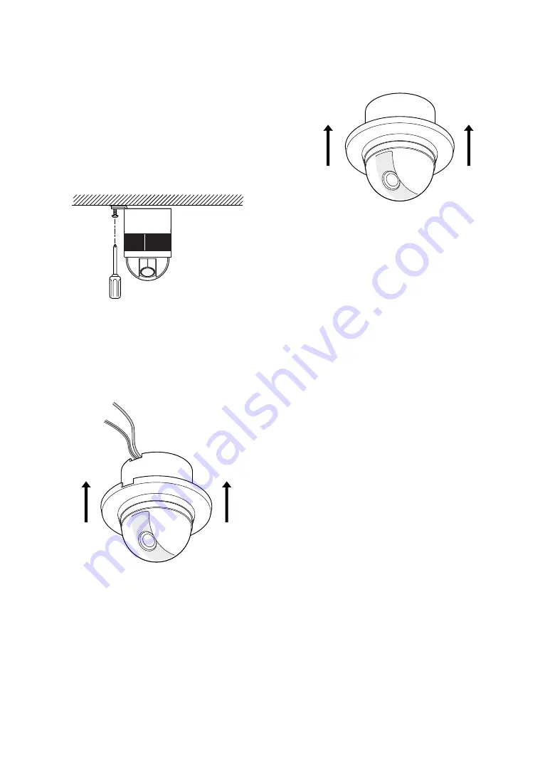
6. Fix the decoration cover to the camera

mounting base.

a. Sideway Cable Exit

Pass the cables through the cutout made in
the diecast case and decoration cover.

b. Top Cable Exit

Push the decoration cover against the cam-
era mounting base.

5. Tighten the fixing screw M3 (provided).

Notes:

(1) Tighten the camera fixing screw with a

screwdriver.

(2) Follow the instructions given here to

ensure that the camera and camera
mounting base are installed safely.

(3) When removing the camera from the

camera mounting base, loosen and
press up the camera fixing screw (M3)
by using a screwdriver.

Summary of Contents for WV-CS320

Page 1: ... connect or operate this product please read these instructions carefully and save this manual for future use Model No WV CS320 WV CS324E Colour CCTV Camera Operating Instructions FRANÇAIS DEUTSCH ENGLISH ESPAÑOL ITALIANO ...

Page 2: ...e or electric shock do not expose this appliance to rain or moisture CAUTION Before attempting to connect or operate this product please read the label on the bottom Wij verklaren als enige aansprakelijke dat het product waarop deze verklaring betrekking heeft voldoet aan de volgende normen of andere normatiefve dokumenten overeenkomstig de bepalingen van Richtlijnen 73 23 EEC en 89 336 EEC Vi erk...

Page 3: ... Display 14 Presetting 15 Deleting Preset Positions 19 Home Position Setting HOME POSITION 19 Self Return Setting SELF RETURN 19 Auto Mode Selection AUTO MODE 20 Flip A Chip Setting 22 Cleaning CLEANING 22 Image Hold IMAGE HOLD 23 Camera Setting 23 INSTALLATION 32 CONNECTIONS 35 PREVENTION OF BLOOMING AND SMEAR 36 SPECIFICATIONS 36 ACCESSORIES 37 OPTIONAL ACCESSORIES 37 APPENDIX 38 ENGLISH ...

Page 4: ...es delete the preset position and set the cor rect preset position newly You cannot exchange the preset data between WV CS320 and other models 4 High quality picture of 752 x 582 pixels Minimum illumination of 2 0 lx Flip a chip allows a 180 tilting to trace objects passing under the camera Auto pan BLC FEATURES Panasonic presents highly advanced CCTV tech nology that meets the demands of new and ...

Page 5: ...n of the colour filter in the CCD 7 Do not install this camera upside down This camera is designed for mounting on the ceiling or wall Consult an expert on the load bearing capacity of the installation surface and struc ture If the surface is not strong enough the camera may fall down Refer to the product specifications for weights 8 Do not operate the camera beyond the specified temperature humid...

Page 6: ...ble for any damage whether direct or indirect caused by using the product for business transac tion or security or malfunctioning of this product 12 Self diagnosis Function If the camera continues operating abnormal ly for 30 seconds or more due to such acci dent as external noise the camera will auto matically reset its power In the case it hap pens frequently check if there would be any environm...

Page 7: ...rting Point y Fall Prevention Wire u Decoration Cover i Dome Cover q Video Output Connector w Power Cable for WV CS320 e Power Cable for WV CS324E r Camera Mounting Base CONSTRUCTION q w e r t u y i WV CS320 WV CS324E ...

Page 8: ...Position Selection Self Return Setting FLIP A CHIP ON OFF PRESET Menu Auto Pan Setting Menu Auto Mode Selection Cleaning ON OFF Image Hold ON OFF Position Setting Light Control ALC MANUAL MAP Menu Preset No SET Menu Preset ID Setting Preset ID Editing Manual Iris Adjustment BLC ON BLC OFF Manual Mask Area Selection Manual Level Adjustment Contrast Preset Setting Menu AF Mode AUTO MANUAL Setup Menu...

Page 9: ...vely in the table System Controller WV CU CJ 550 ALARM BUSY F1 F2 SET WIDE AF ZOOM TELE ESC SLOW ALT BACK SEQ ACK RESET FORWARD SEQ DEC 1CAM AUX INC 1CAM STOP 2 1 F3 F4 1 2 3 4 5 6 7 8 9 MON 0 CAM CLOSE OPEN IRIS PRESET FAR FOCUS NEAR System Controller WV CU C 1 2 3 4 6 7 8 9 0 5 SHIFT OPERATE ALARM RESET SLOW SUSPEND CAMERA SETUP PATROL PLAY PROGRAM PRESET CAMERA FUNCTION SETUP ESC HOME SET PRESE...

Page 10: ...ng the lens iris See page 18 for the setting Home Position HOME POSITION A home position is the camera s basic position It returns to this position automatically when a specific time has elapsed after a manual operation This setting functions only when AUTO MODE is OFF See page 19 for the setting Self Return SELF RETURN Self return is the time out parameter for returning to the home position In ON...

Page 11: ...backlight compensation Backlight compensation is available in the ALC mode It eliminates strong background light which makes the camera picture dark such as a spotlight MANUAL The lens iris is fixed at the value that you have set regardless of the brightness of an object ALC Mode with BLC ON In normal use the important object in a scene is placed in the centre of the monitor screen In the factory ...

Page 12: ...e balance is approx 2 600 to 6 000 K Proper white balance may not be obtained under the following conditions 1 The colour temperature is out of the 2 600 to 6 000 K range 2 When the scene contains mostly high colour temperature bluish objects such as a blue sky 3 When the scene is dim In these cases select the AWC mode Automatic White Balance Control AWC In this mode accurate white balance is obta...

Page 13: ...WV CU360C Press the CAM SETUP key while holding down the SHIFT key to open the SETUP menu WV CU161C Press the CAMERA SETUP key for 2 seconds or more to open the SETUP menu WV RM70 1 Turn the MODE SELECTION switch to NORMAL or ALARM OFF 2 Press the PROG switch for 2 seconds or more to open the Program Menu 3 Move the cursor to Camera Set Up Menu and press the SET switch to open the SETUP MENU Subme...

Page 14: ... appears 2 Select panning tilting positions by moving the joystick up and down right and left and press the CAM SET key The positions are set and the screen returns to the position setting menu Note When you press the CAM SET key the camera might move slightly to memorize the nearest panning tilting position 3 To Set the Lens Zoom and Focus Positions 1 Move the cursor to PUSH SET for ZOOM FOCUS an...

Page 15: ...ve the cursor to RET and press the CAM SET key to return to the preset setting menu Preset Identification Setting PRESET ID 1 Move the cursor to PRESET ID on the preset setting menu and select ON or OFF by moving the joystick to the right or left The factory default setting is OFF 2 Press the CAM SET key to display the preset ID setting menu PUSH SET PUSH SET POSITION 1 PAN TILT ZOOM FOCUS RET FLO...

Page 16: ...ct a new character by using the joystick 3 Press the CAM SET key to determine the Preset ID To Delete an Entered Preset ID Move the cursor to RESET and press the CAM SET key PRESET NO 1 0123456789 ABCDEFGHIJKLM NOPQRSTUVWXYZ ÄÜÖÆÑÅ SPACE COPY POSI RET RESET PRESET NO 1 0123456789 ABCDEFGHIJKLM NOPQRSTUVWXYZ ÄÜÖÆÑÅ SPACE COPY POSI RET RESET PRESET NO 1 0123456789 ABCDEFGHIJKLM NOPQRSTUVWXYZ ÄÜÖÆÑÅ ...

Page 17: ...screen Set the lens iris level as desired by moving the joystick to the right or left Auto Focus Setting AF MODE 1 Move the cursor to AF MODE and select the following mode by moving the joystick to the right or left The factory default setting is MANUAL MANUAL AF does not work after moving to a preset position AUTO AF works after moving to a preset position To confirm auto focus operation press CA...

Page 18: ...t a return time by moving the joystick to the right or left The factory default setting is OFF Return time changes as follows 2MIN 3MIN 5MIN 10MIN 60MIN 30MIN 20MIN 1MIN OFF MIN stands for minute s Note The camera will return to the auto mode if that is set to AUTO PAN when a specific time has elapsed after a manual operation PRESET NO 1 POSITION SET O PRESET ID ON O ALC MANUAL ALC O AF MODE MANUA...

Page 19: ... to POSI TION 4 To set a panning speed Move the cursor to SPEED and set a panning speed by moving the joystick to the right or left The panning speed increases when the joystick is moved to the right and decreases when it is moved to the left Notes If the panning range is changed after the camera has not panned for a long time or has been panning in the same panning range the picture may not be cl...

Page 20: ...o OFF before ENDLESS is set to ON OFF The camera pans from the starting point to the endpoint and rotates backward to the starting point This movement is repeated over and over 7 To set a dwell time Move the cursor to DWELL TIME and select a dwell time by mov ing the joystick to the right or left The factory default setting is 2S Dwell time changes as follows Notes When the panning tilting zooming...

Page 21: ...leaning CLEANING Built in electric mechanical contacts are refreshed at regular intervals approx 7 days if CLEANING is set to ON A dry contract adversely affects picture quality and motors operation 1 Move the cursor to CLEANING and select ON or OFF by moving the joystick to the right or left The factory default setting is OFF ON The contacts are cleaned for approx 1 minute CLEANING disappears whe...

Page 22: ...he desired character using the joystick and press the CAM SET key 2 The selected character appears in the editing area The pointer in the editing area moves to the right automatically at this moment To enter a blank select SPACE 3 Repeat the above procedure until all characters are entered Note Refer to pp 17 and 18 for POSI RET and RESET SET UP MENU PRESET 1 O MAP O HOME POSITION OFF SELF RETURN ...

Page 23: ... key Press the OPEN or CLOSE key on the controller for iris adjustment 1 ALC Mode with BLC ON 1 Press the CAM SET key after selecting ALC The ALC CONT menu appears 2 Move the cursor to the BLC and select ON 3 If you want to adjust the video output level move the I cursor for LEVEL Adjust it to the desired level by using the joystick 4 Move the cursor to RET and press the CAM SET key to return to t...

Page 24: ...FF 2 ALC Mode with BLC OFF 1 Move the cursor to the BLC and select OFF When you select MANUAL BLC is not available The MASK SET appears on the menu 2 Move the cursor to MASK SET and press the CAM SET key The 48 mask areas appear on the monitor screen The cursor is blink ing in the top left corner of the screen 3 To mask an area where backlight is bright move the cursor to the area and press the CA...

Page 25: ... switched to the multi plexed vertical drive pulse VD2 regardless of the selected sync mode Line lock Sync Mode LL 1 Move the cursor to SYNC and select LL by using the joystick LL sync mode is not available when the multiplexed vertical drive VD2 pulse is supplied 2 After selecting LL press the CAM SET key The SYNC menu appears on the monitor screen 3 Supply the video output signal of the camera t...

Page 26: ...steps of 22 5 degrees 16 steps with the joystick Note After the 16 steps the adjustment returns to the first step 7 Move the cursor to FINE by using the joystick 8 Use the joystick to match the vertical phase for both video output signals as closely as possible SYNC V PHASE COARSE FINE RET 1 1 16 SYNC menu 1 1 16 0 degrees 2 1 16 22 5 degrees 16 1 16 337 5 degrees SYNC V PHASE COARSE FINE RET 1 1 ...

Page 27: ...ng the joy stick The factory default setting is ATW The white balance of the camera is automatically set 2 For fine adjustment of the ATW press the CAM SET key The ATW fine adjustment menu appears on the monitor screen 3 Move the cursor to RET by using the joystick and press the CAM SET key to return to the SET UP menu 2 Automatic White Balance Control Mode AWC 1 Move the cursor to WHITE BAL and s...

Page 28: ...uto Focus Setting AF MODE 1 Move the cursor to AF MODE and select the following mode by moving the joystick to the right or left The factory default setting is MANUAL 2 To confirm auto focus operation press the CAM SET key Note The auto focus lens may not function properly in the AUTO mode under the following conditions 1 Dirt or water on window glass The auto focus may focus on the dirt or water ...

Page 29: ...econds or more 4 To Restore the Camera Default Position REFRESH Move the cursor to REFRESH by using the joystick and press the F2 button of the WV CU550CJ For the WV RM70 WV CU360C or WV CU161C keep pressing the Right and Left switches simultaneously for 2 seconds or more 5 Camera Resetting CAMERA RESET Move the cursor to CAMERA RESET by using the joystick and press the F3 button of the WV CU550CJ...

Page 30: ...e Never face the camera at a place exposed to light sources for a long time If light sources such as spot light cause burn in on the display screen part of image may discolour due to deterioration of colour filter in CCD when changing aim of the camera etc Reset to the Factory Default Settings Any of the above settings plus the ALC MANUAL level control and phase adjustments can be reset to the fac...

Page 31: ...stallation and connection work should be done by qualified service person nel or system installers and should conform to all local codes Be sure to switch the camera off before installation and connection Do not install the camera near the air outlet of an air conditioner Camera mounting base Camera Camera mounting base Fixing screw Loosen and push INSTALLATION 1 Disassembling the Camera 1 Loosen ...

Page 32: ...ention wire 3 Hook the fall prevention wire on the camera mounting base 15 Cautions Use the supplied dust protection sheet if the camera mounting base is liable to be exposed to a dusty atmosphere Remove the cover from the dust protection sheet then stick the sheet on the camera mounting base Remove the sheet before mounting the cam era on the base While the camera is separated from the base keep ...

Page 33: ...e decoration cover against the cam era mounting base 5 Tighten the fixing screw M3 provided Notes 1 Tighten the camera fixing screw with a screwdriver 2 Follow the instructions given here to ensure that the camera and camera mounting base are installed safely 3 When removing the camera from the camera mounting base loosen and press up the camera fixing screw M3 by using a screwdriver ...

Page 34: ... a one time procedure Do not shrink the cable entry seal until it has been ascertained that the unit is functioning CONNECT THIS TO 24 V AC CLASS 2 POWER SUPPLY ONLY Contact Insert Up A Approx 3 mm 0 1 inch Insert the wire until A position and clamp the contacts Wire Up Wire Contact Up Contact Wire Approx 3 mm 0 1 inch Insert the wire until A position and clamp the contacts 1 3 2 4 24 V AC Power S...

Page 35: ...rating temperature Weight selectable ON OFF SETUP MENU x10 internal line lock multiplexed vertical drive VD2 50 00 Hz 1 0 V p p PAL composite 75 Ω more than 480 lines at centre more than 400 lines at centre 50 dB AGC OFF weight on 2 0 lx 0 2 foot candle AGC ON HIGH approx 3 8 s TELE WIDE in manual mode approx 3 0 s FAR NEAR in manual mode automatic open close is possible manual 1 1 4 WIDE to 2 0 T...

Page 36: ...tilt lens 10 preset positions home position Panning angle setting Panning mode Panning speed Tilting range Tilting mode Tilting speed Auto focus ACCESSORIES Decoration cover 1 pc Connector for 24 V AC only for WV CS324E 1 pc MANUAL AUTO OFF AUTO PAN ON OFF preset ID camera ID characters ON OFF ON OFF Auto mode Flip A Chip Camera ID BLC Cleaning OPTIONAL ACCESSORIES Dome cover approx 60 smoked type...

Page 37: ...1 1 0 CAM FUNC IRIS Open 1 6 9 CAM FUNC Close 1 7 0 CAM FUNC EL SHUTTER On 1 7 1 CAM FUNC Off 1 7 2 CAM FUNC Speed Up 1 7 3 CAM FUNC Speed Down 1 7 4 CAM FUNC AGC On 1 7 5 CAM FUNC Off 1 7 6 CAM FUNC LL SYNC phase INC 1 8 5 CAM FUNC DEC 1 8 6 CAM FUNC PAN 180 turn 1 8 7 CAM FUNC CLEANING On 1 8 8 CAM FUNC Off 1 8 9 CAM FUNC APPENDIX Shortcuts Shortcut operations are available to controllers having...

Page 38: ...ed in Japan Gedruckt in Japan Imprimé au Japon Impreso en Japón Stampato in Giappone Matsushita Electric Industrial Co Ltd Web Site http www panasonic co jp global 2002 Matsushita Communication Industrial Co Ltd All rights reserved ...

Reviews: