20
■
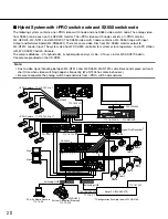
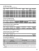
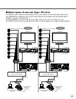
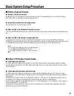
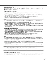
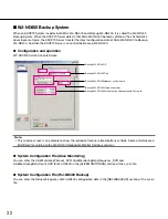
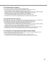
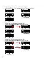
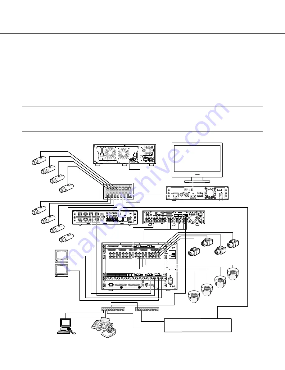
Hybrid System with i-PRO switch node and SX650 switch node
The following system contains one i-PRO video switch node and one SX650 video switch node. The analog video
from SX650 can be seen on the GXD400 monitor. The i-PRO video switch node consists of i-PRO cameras,
WJ-GXD400, WJ-NT314 and WJ-ND400. The SX650 video switch node contains a WJ-SX650 cage with Input,
Output and Network board (WJ-PB65E01). There are some video links from WJ-SX650 monitor output to
WJ-NT314 coaxial Input. The system also has WV-CU950 controller for system or local operators, and a PC station
with WV-ASC970 Admin Console.
The sample database – 01=hybrid.adm, #=hybrid.gdm-and sys.ini file – 01A=sys.ini-for WV-ASC970 Admin
Console are provided on the CD-ROM.
Note:
• Due to video signal handling between WJ-NT314 and WJ-SX650, WJ-NT314 sometimes sends green picture in
short time when video switching happens frequently. (WJ-NT304 has same behaviors.)
• Be sure to separate the analog switch node network from i-PRO switch node network.
WJ-SX650
WJ-SX850
3
C
1
2
B
1
2
3
AC IN
3
2
1
A
ALARM IN
EXTENSION 3 IN
EXTENSION 2 IN
4
3
2
1
DATA
DATA
1
2
3
4
DATA 4
HDR4/TMNL8
HDR2/TMNL4
DATA 3
HDR3/TMNL7
HDR1/TMNL3
DATA 2
TMNL6
TMNL2
DATA 1
TMNL5
Video Output Board 2
Video Output Board 1
CAMERA IN
ALARM OUT 2
ALARM OUT 1
SERIAL
10/100 BASE-T
DATA
G
AUDIO OUT VIDEO OUT
OUT
IN
12V
IN
IN
4
4
OUT
IN
OUT
VIDEO
AUDIO
ALARM/CONTROL 10/100BASE-T RS-485
3
3
2
2
1
1
4 3 2 1 4 3 2 1
G
G
OUT
IN
SIGNAL
GND
12V IN
PC with Admin Console
172.18.0.9
System Controller (Ethernet)
172.18.0.10
Switching HUB
Switching HUB
Digital Disk Recorder*1
172.18.0.1
172.16.192.1
192.168.200.200
L3SW
WJ-GXD400
WV-LW2200
WJ-ND400
172.16.192.22
192.168.200.1
WJ-NT314
Sever PC (WV-ASC970)
*1 Configuration Example shows WJ-HD316A
Cam5
Cam1
Cam2
Cam3
Cam4
Cam6
Cam7
Cam8
Mon1
Mon2
WV-CU950
8
7
6
5
i-PRO Camera 172.16.192.4 to 7
172.16.192.21
172.16.192.20
172.18.0.60
i-PRO Camera 172.16.192.8 to 11
4
3
2
1

