background image

51

Camera Function Control

Camera Setup

The following function requires the use of cameras
equipped with this specific feature.

1. Select the desired monitor and camera.

Refer to the Monitor Selection and Camera Selection.

2. Pressing the 

[STOP]

button while holding down the

[SHIFT]

button will open the Camera Setup Menu on

the active monitor.
The STOP indicator will light.

3. Select the desired item in the menu by moving the

Joystick Controller 

UP

and 

DOWN

, and then select the

desired parameter (or mode) in the menu by moving
the Joystick Controller 

L

and 

R

.

Press the 

[CAMERA (ENTER)]

button to execute the

currently highlighted selection and to enter a submenu
of the Camera Setup Menu, or press the 

[CLEAR

(ESC)]

button to leave from the currently selected

menu and return to the previous page of the menu.

4. Press the 

[RESET]

button in the menu to reset the

parameter of a selected item to the factory default set-
ting or enter the Special Camera Menu when the cursor
is positioned on SPECIAL in the menu.
Pressing the 

[RESET]

button while holding down the

[SHIFT]

button will restore all factory default settings.

Notes:

• Refer to the Operating Instructions of the selected

camera for more details.

• Moving the joystick while holding down the 

[SHIFT]

button will move the camera smoothly for preset-
ting the position in the camera setup menu.

5. To close the Camera Setup Menu, press the 

[PAUSE]

button while holding down the 

[SHIFT]

button.

The STOP indicator will go off.

RESET

ACK

ALARM

DISARM

ALL RESET

NEXT

PREV

S-CTL ID

STOP

PAUSE

CAM MENU ON

CAM MENU OFF

TOUR

SEQ

GROUP

SEQ

MONITOR

LOCK

OSD SERVICE

CAM FUNC

OSD

OPE ID

GROUP PRESET

LOG OUT

F1

F2

PROGRAM

PRESET

CALL

PRESET

AUX1 OFF

ALM S

CAM ID

T&D

AUX1 ON

VLD S

GEN

WIPER

SYS S

AUX2 OFF

ALM H

AUX2 ON

VDL H

ALL

SHIFT

BLK

EXIT

CLEAR

(ESC)

DEF OFF

DEF ON

CAMERA

(ENTER)

AUTO

PAN

MON STATUS

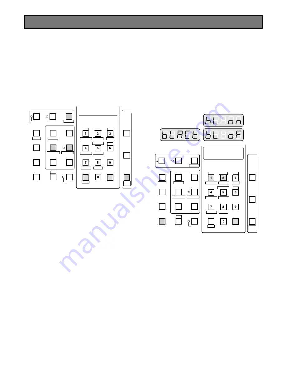
Changing to Black and White
Pictures

The following function is available only when specified cam-
eras having a color-black and white switching feature are
used.

1. Select the desired monitor and camera.

Refer to the Monitor Selection and Camera Selection.

2. Press the 

[F2]

button two times.

"BLACT" as shown in the figure will appear on the LED
display of the controller.

3. Press the 

[1]

button to change the picture from color to

black and white on the active monitor.
"BL ON" appears on the LED display to indicate the
selected mode.

4. Press the 

[2]

button to change black and white to color

picture on the active monitor.
"BL OF" appears on the LED display to indicate the
selected mode.

5. To exit from the mode, press the 

[CLEAR (ESC)]

but-

ton.

Note:

When the black and white parameter is set

AUTO in the camera setup menu, this function is
disabled.

RESET

ACK

ALARM

DISARM

ALL RESET

NEXT

PREV

S-CTL ID

STOP

PAUSE

CAM MENU ON

CAM MENU OFF

TOUR

SEQ

GROUP

SEQ

MONITOR

LOCK

OSD SERVICE

CAM FUNC

OSD

OPE ID

GROUP PRESET

LOG OUT

F1

F2

PROGRAM

PRESET

CALL

PRESET

AUX1 OFF

ALM S

CAM ID

T&D

AUX1 ON

VLD S

GEN

WIPER

SYS S

AUX2 OFF

ALM H

AUX2 ON

VDL H

ALL

SHIFT

BLK

EXIT

CLEAR

(ESC)

DEF OFF

DEF ON

CAMERA

(ENTER)

AUTO

PAN

MON STATUS

Summary of Contents for WJMPU955 - PROCESSING UNIT - TMU

Page 1: ...operate this product please read these instructions carefully and save this manual for future use Model No WJ MPU955 Central Processing Unit Operating Instructions RESET FAN ALARM HDD ACTIVE OPERATE C...

Page 2: ...he unit whenever the power cord is inserted into the power source however the unit is operational only when the ON OFF switch is in the ON position Unplug the power cord to disconnect the main power f...

Page 3: ...cian for replacement of the obsolete outlet 10 Protect the power cord from being walked on or pinched particularly at plugs convenience receptacles and the points where they exit from the apparatus 11...

Page 4: ...a Selection 29 Priority Lock 30 Display Setting for Controller 31 Adjustment of LCD Display 31 Adjustment of LED Display 31 IDs Display Function 31 Controlling Camera Site Accessories 32 Lens Control...

Page 5: ...s The replacement cost of the hard disk drive is not covered by the warranty even if it needs to be done within the warranty period Consult your dealer for servicing Network Environment The Network Se...

Page 6: ...WJ MPU955 is turned on The power switch of the CPU is located underneath the front panel Remove the front panel by removing the two screws on the panel w Reset Button RESET The RESET button w is reces...

Page 7: ...to 12 controllers can be connected i Peripheral Interface Ports PERIPHERAL INTER FACE RS 232C These ports i are reserved for future use or factory tests o Redundant CPU Selector REDUNDANT CPU The sele...

Page 8: ...e default system configu ration file set by the factory at the time of shipping To mod ify the default configuration file you can use the administra tion tool Admin Console From the Admin Console main...

Page 9: ...controllers RS485 Based Controller Setup To add a CU360C controller to the system use the adminis tration tool Admin Console and add an entry to the system controller database You need to assign a con...

Page 10: ...ports of CPU Switch Unit Set the redundant CPU selector to YES on the rear of the A and B CPU units PUSH FUSE AC IN TARGET DATA 1 MAIN CPU ACT CAITION MAIN CPU STANDBY PERIPHERAL INTERFACE RS 232C SY...

Page 11: ...witch Nodes from the Domain menu select Digital GX from the sub menu that appears and then enter the information for the encoder device Please note you need to know the Rotary Switch SW1 A B C reading...

Page 12: ...168 1 10 192 168 3 11 192 168 4 11 192 168 1 11 192 168 4 1 192 168 3 1 192 168 1 1 192 168 2 1 192 168 200 1 SIGNAL GND POWER ON OFF 3 3 1 4 2 1 4 2 VIDEO OUT AUDIO OUT MIX RESET 1000BASE T 100BASE T...

Page 13: ...1 PERIPHERAL INTERFACE RS 232C RS 485 SYSTEM CONTROLLER 2 1 SATELLITE STANDALONE YES NO AC IN 125V 6 3A SIGNAL GND WJ GXD900 Switching HUB POWER ON OFF SIGNAL AUDIO IN VIDEO OUT VIDEO IN 100BASE TX R...

Page 14: ...om the TMU main menu and enter the IP address of the CPU unit See the Time Management Utility Installation and configuration manual for more details See reference 4 Setup Layer 3 Switching L3SW Layer...

Page 15: ...R NEAR AUTO FOCUS ZOOM DOWN UP R L TELE WIDE ALARM ACK RESET ALL RESET ARM GROUP PRESET PREV S CTL ID OPE ID NEXT GROUP SEQ PAUSE STOP TOUR SEQ REV RUN FWD RUN OSD F 1 F 2 F 3 CMENU OFF F 4 CMENU ON F...

Page 16: ...OWN UP R L TELE WIDE ALARM ACK RESET ALL RESET ARM GROUP PRESET PREV S CTL ID OPE ID NEXT GROUP SEQ PAUSE STOP TOUR SEQ REV RUN FWD RUN OSD F 1 F 2 F 3 CMENU OFF F 4 CMENU ON F 5 F 6 CLOSE IRIS WIPER...

Page 17: ...ss monitor select monitor lock on screen display on and off time and date on and off Operator Priority The system administrator can assign a priority to each operator When two operators compete for sy...

Page 18: ...admin istration tool Admin Console Control Alarm Action The system supports the following alarm actions Camera spots Tour sequences Text display The system supports up to 10 alarm actions and allows o...

Page 19: ...255 255 255 0 192 168 200 200 Interface0 is an interface for GX devices Interface1 172 18 0 1 255 255 0 0 172 18 0 1 Interface1 is an interface for system controller Interface2 172 16 192 1 255 255 0...

Page 20: ...tly supported Set SSntp to the same interface_num for all system CPUs SSntp 2 Not currently supported Set SNMPAgent to the same interface_num for all system CPUs SNMPAgent 2 1 means interface1 in INTE...

Page 21: ...below to make this section active Required only for PSDIC RMS NumDedicatedRecorders 0 NumBackupRecorders 0 Review 0 0 0 Backup 0 0 0 IdleSource 0 Links 0 0 LOG section This section sets the frequency...

Page 22: ...It is not required unless System defaults are not acceptable Delete the single asterisks below to make this section active Alarm Text Display format Format AlarmTextDisplay option option 0 Display Ala...

Page 23: ...not required unless System defaults are not acceptable Delete the single asterisks below to make this section active This section lists user defined client SNTP values sync rates and an external serve...

Page 24: ...4 5 6 7 8 9 10 11 12 13 14 15 16 Switch Digital Digital Digital Digital Digital Digital Digital Digital Digital Digital Digital Digital Digital Digital Digital Digital Ports 1 2 3 4 5 6 7 8 9 10 11 1...

Page 25: ...00 00 00 00 00 00 00 00 00 00 00 00 00 00 00 00 00 00 00 00 00 00 00 00 00 00 00 00 00 00 00 00 00 00 00 00 00 00 00 00 00 00 00 00 00 00 00 00 00 00 00 00 00 00 00 00 00 00 00 00 00 00 00 00 00 00 0...

Page 26: ...26...

Page 27: ...27 OPERATING PROCEDURES with WV CU850...

Page 28: ...isplays will appear on the LCD display of the system controller 3 Select your registered operator ID number up to 5 dig its by pressing the numeric keys then press the CAMERA ENTER key PASSWORD will a...

Page 29: ...ENTER key will replace the currently selected cam era with the next lower camera number Note The CAMERA BUSY indicator lights if the cam era is selected by a higher priority operator Control of the s...

Page 30: ...f the Priority Lock mode is selected the monitor num ber with L sign is displayed on the active monitor and the MONITOR LOCK indicator on the controller is on Releasing Priority Lock 1 Select the desi...

Page 31: ...g functions Operator ID Display Pressing the GROUP PRESET key while holding down the SHIFT key will display the Operator ID number on the LCD display Controller ID Display Pressing the PREV key while...

Page 32: ...WIDE key has the reverse effect 4 Press the IRIS CLOSE OPEN keys to close open the lens iris Adjust the lens iris by using these keys to obtain the proper picture exposure By pressing these keys at t...

Page 33: ...unction requires the use of cameras equipped with this specific feature 1 Select the desired monitor and camera Refer to the Monitor Selection and Camera Selection 2 Select the preset position number...

Page 34: ...the user s auxiliary switch 1 of the Receiver Pressing the LOG OUT key holding down the SHIFT key will turn off the user s auxiliary switch 1 of the Receiver 3 Press the PGM PRESET key while holding d...

Page 35: ...tures The following function is available only when specified cam eras having a color black and white switching feature are used 1 Select the desired monitor and camera Refer to the Monitor Selection...

Page 36: ...own in the figure will appear on the LCD display of the controller 3 Press the assigned numeric key shown below to acti vate the panning function of the selected camera 1 Activates Auto Pan 2 Activate...

Page 37: ...n the active monitor The P sign indicating the pause status is displayed at the Tour Sequence Number on the active monitor 5 Press the FWD RUN key to restart a Tour Sequence forward from the next step...

Page 38: ...he OSD key will toggle the general status display on the active mon itor on and off Monitor Display Control 07 07 1999 03 37 21 PM M AREA1 ALM T R A C CAMERA TITLE CAM ID VLD S T D ALM S GEN SYS S ALA...

Page 39: ...TITLE CAM ID VLD S T D ALM S GEN SYS S ALARM 0 8 7 MSTATUS VLD H ALL ALM H BLK 5 9 6 4 2 3 1 SHIFT CLEAR ESC EXIT GROUP PRESET PREV S CTL ID OPE ID NEXT GROUP SEQ PAUSE STOP TOUR SEQ REV RUN FWD RUN O...

Page 40: ...ys fol lowed by the ALARM key 2 Select the alarm action number by pressing the numer ic key then press the ACK key to acknowledge the activated alarm manually The acknowledged alarm picture is display...

Page 41: ...prompts and hold it then press the CLEAR key Repeat this procedure The prompts on the LCD display will be replaced by pressing the CLEAR key as shown below Center Press CLR Up Press CLR Right Press CL...

Page 42: ...42...

Page 43: ...43 OPERATING PROCEDURES with WV CU360C...

Page 44: ...ler 4 Select your registered Password up to 5 digits by pressing the numeric buttons then press the CAM ERA ENTER button If operator ID and password are correct READY will appear on the LED display No...

Page 45: ...ID STOP PAUSE CAM MENU ON CAM MENU OFF TOUR SEQ GROUP SEQ MONITOR LOCK OSD SERVICE CAM FUNC OSD OPE ID GROUP PRESET LOG OUT F1 F2 GEN WIPER SYS S AUX2 OFF ALM H MON STATUS AUX2 ON VDL H ALL SHIFT BLK...

Page 46: ...the selected camera number is not valid or parti tioned the PROHIBITED indicator is on and the number on the LED display will blink for about 3 seconds Return to step 2 and select a new camera number...

Page 47: ...iority Lock mode is selected the monitor num ber with L sign is displayed on the active monitor and the MONITOR LOCK indicator on the controller is on Releasing Priority Lock 1 Select the desired moni...

Page 48: ...ct closer Pressing the WIDE button has the reverse effect 4 Press the IRIS CLOSE OPEN buttons to close open the lens iris Adjust the lens iris by using these buttons to obtain the proper picture expos...

Page 49: ...650 Series Camera is connected to the Encoder Pan Tilt Control Call Preset Position The following function requires the use of cameras equipped with this specific feature 1 Select the desired monitor...

Page 50: ...in the system and the specified camera housing is installed Wiper Control 1 Select the desired monitor and camera Refer to the Monitor Selection and Camera Selection 2 Pressing the 3 button while hol...

Page 51: ...button The STOP indicator will go off RESET ACK ALARM DISARM ALL RESET NEXT PREV S CTL ID STOP PAUSE CAM MENU ON CAM MENU OFF TOUR SEQ GROUP SEQ MONITOR LOCK OSD SERVICE CAM FUNC OSD OPE ID GROUP PRE...

Page 52: ...SD OPE ID GROUP PRESET LOG OUT F1 F2 PROGRAM PRESET CALL PRESET AUX1 OFF ALM S CAM ID T D AUX1 ON VLD S GEN WIPER SYS S AUX2 OFF ALM H AUX2 ON VDL H ALL SHIFT BLK EXIT CLEAR ESC DEF OFF DEF ON CAMERA...

Page 53: ...D display 5 Press the TOUR SEQ button to restart a Tour Sequence forward from the next step that was previ ously paused by pressing the PAUSE button 6 Press the TOUR SEQ button while holding down the...

Page 54: ...itor Display Control 07 07 1999 03 37 21 PM M AREA1 ALM T R A C CAMERA TITLE AUX1 OFF ALM S CAM ID T D AUX1 ON VLD S NEXT PREV S CTL ID STOP PAUSE CAM MENU ON CAM MENU OFF TOUR SEQ GROUP SEQ MONITOR L...

Page 55: ...V S CTL ID STOP PAUSE CAM MENU ON CAM MENU OFF TOUR SEQ GROUP SEQ MONITOR LOCK OSD SERVICE CAM FUNC OSD OPE ID GROUP PRESET LOG OUT F1 F2 GEN WIPER SYS S AUX2 OFF ALM H MON STATUS AUX2 ON VDL H ALL SH...

Page 56: ...ssing the numeric buttons fol lowed by the ALARM button 2 Select the alarm action number by pressing the numer ic button then press the ACK button to acknowledge the activated alarm manually The ackno...

Page 57: ...57 TROUBLESHOOTING...

Page 58: ...U is not in Active state Symptom Possible cause Possible solution Reference page 10 In case of standard system no redundant CPU check the redundant CPU selector It must be in NO position In case of re...

Page 59: ...e correct controller Ethernet address CU360C controller fails to dis play No User while power is on reference 1 9 Check the RS485 connection between the WV CU360C and CPU unit Check the controller dat...

Page 60: ...k for Encoder and Decoder control 1 port other 1 port RS 232C Port 9 pin D sub connector x3 Ambient Operating Temperature 10 C 50 C 14 F 122 F Ambient Operating Humidity Less than 90 Dimensions 16 15...

Page 61: ......

Page 62: ...ications Security Company Unit of Matsushita Electric Corporation of America Security Systems Group www panasonic com cctv Executive Office One Panasonic Way 3E 7 Secaucus New Jersey 07094 Zone Office...

Reviews: