background image

34

Technical Information

Input signal that can be displayed

 Mark: Applicable input signal for Component (Y, P

B

, P

R

), HDMI and PC (D-sub 15P)

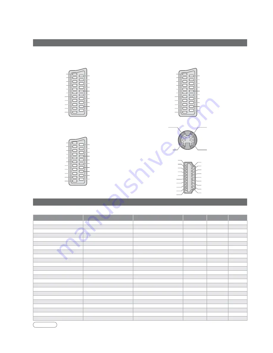
SCART, S-video and HDMI terminal information

Socket Earth
CVBS out (video)
CVBS earth
Red in
Red earth
Green in
Green earth
Blue in
Blue earth
Audio out (L)
Audio out (R)

CVBS in (video)
RGB status earth
Status RGB
Earth
--
--
Status CVBS
Audio in (L)
Audio earth
Audio in (R)

21
19
17
15
13
11
9
7
5
3
1

20
18
16
14
12
10
8
6
4
2

Ŷ

AV1 

SCART terminal 

(RGB, VIDEO)

Suitable inputs for AV1 include RGB (Red / Green / Blue).

Socket Earth
CVBS out (video)
CVBS earth
S.C. - in
Earth
--
Earth
--
Earth
Audio out (L)
Audio out (R)

CVBS in (video)
Earth
--
Earth
--
Q-Link data
Status CVBS
Audio in (L)
Audio earth
Audio in (R)

21
19
17
15
13
11
9
7
5
3
1

20
18
16
14
12
10
8
6
4
2

Ŷ

AV2 

SCART terminal 

(VIDEO, S-VIDEO, Q-Link)

AV2 - Pins 15 and 20 are dependent on AV2 S-VHS / 
VIDEO switching.

Chrominance in

Socket Earth
CVBS out (video)
CVBS earth
Red in, S.C. - in
Red earth
Green in
Green earth
Blue in
Blue earth
Audio out (L)
Audio out (R)

CVBS in (video)
RGB status earth
Status RGB
Earth
--
Q-Link data
Status CVBS
Audio in (L)
Audio earth
Audio in (R)

21
19
17
15
13
11
9
7
5
3
1

20
18
16
14
12
10
8
6
4
2

Luminance in

Chrominance earth

Luminance earth

Ŷ

AV4 

S-VIDEO 4 pin terminal

Ŷ

AV3 

SCART terminal 

(RGB, VIDEO, S-VIDEO, Q-Link)

AV3 - Pins 15 and 20 are dependent on AV3 S-VHS / 
VIDEO switching.

Hot Plug Detect
DDC/CEC Ground
SCL
CEC
TMDS Clock Shield
TMDS Data0

í

TMDS Data0+
TMDS Data1 Shield
TMDS Data2

í

TMDS Data2+

+5V Power
SDA
Reserved (in cable but N.C. on device)
TMDS Clock

í

TMDS Clock+
TMDS Data0 Shield
TMDS Data1

í

TMDS Data1+
TMDS Data2 Shield

19
17
15
13
11
9
7
5
3
1

18
16
14
12
10
8
6
4
2

Ŷ

HDMI

terminal

Signal name

Horizontal frequency (kHz)

Vertical frequency (Hz)

Component

HDMI

PC

525 (480) / 60i

15.73

59.94

525 (480) / 60p

31.47

59.94

625 (576) / 50i

15.63

50.00

625 (576) / 50p

31.25

50.00

750 (720) / 60p

45.00

60.00

750 (720) / 50p

37.50

50.00

1,125 (1,080) / 60i

33.75

60.00

1,125 (1,080) / 50i

28.13

50.00

640 × 400 @70 Hz

31.46

70.07

640 × 480 @60 Hz

31.47

59.94

640 × 480 @75 Hz

37.50

75.00

852 × 480 @60 Hz

31.47

59.94

800 × 600 @60 Hz

37.88

60.32

800 × 600 @75 Hz

46.88

75.00

800 × 600 @85 Hz

53.67

85.06

1,024 × 768 @60 Hz

48.36

60.00

1,024 × 768 @70 Hz

56.48

70.07

1,024 × 768 @75 Hz

60.02

75.03

1,024 × 768 @85 Hz

68.68

85.00

1,280 × 1,024 @60 Hz

63.98

60.02

1,366 × 768 @60 Hz

48.36

60.00

Macintosh13” (640 × 480)

35.00

66.67

Macintosh16” (832 × 624)

49.72

74.54

Macintosh21” (1,152 × 870)

68.68

75.06

Note

Signals other than above may not be displayed properly.

The above signals are reformatted for optimal viewing on your display.

Applicable input signal for PC is basically compatible to VESA Timing Standard.

PC signal is magnifi ed or compressed for display, so that it may not be possible to show fi ne detail 
with suffi cient clarity.

Summary of Contents for Vieta TX-26LX600P

Page 1: ...Instructions LCD Television English Please read these instructions before operating your set and retain them for future reference The images shown in this manual are for illustrative purposes only Mo...

Page 2: ...2 Turn your own living room into a movie theatre Experience an amazing level of multi...

Page 3: ...icture sound quality etc Editing and Setting Channels 18 Displaying PC Screen on TV 21 Watching SD Card Videos and photos 22 Recording a Programme on SD Card 24 External Equipment 26 Q Link Control wi...

Page 4: ...r to perform setup Use optional stands mounts p 6 Use only the dedicated stands mounting equipment Handling the mains plug and lead Insert the mains plug fully into the socket outlet If the mains plug...

Page 5: ...Moisture and dust may lead to re or electrical shock First remove the mains plug from the socket outlet Caution The surface of the display panel has been specially treated and may be easily damaged Do...

Page 6: ...g the clamper Do not bundle the RF cable and mains lead together could cause distorted image Fix cables with clampers as necessary When using the optional accessory follow the option s assembly manual...

Page 7: ...Recording To immediately record programme in VCR DVD recorder with Q Link connection p 26 MENU Press to access the Picture Sound and Setup menus Direct channel access During normal TV viewing or when...

Page 8: ...y wired RF cable Rear of the TV Connect to AV2 or AV3 for a unit supporting Q Link p 26 VHF UHF aerial Watching TV To record TV programmes DVD Recorder or VCR Rear terminal portion enlarged view Mains...

Page 9: ...h operations example Sound menu On screen operation guide will help you Auto Setup For Belgium Switzerland and E Eu select the desired language Search and store TV channels automatically These steps a...

Page 10: ...rn power on On Off switch on TV should be On for about 1 second down or in a short time 1 Select from the Programme table Prog Name Chan VCR 1 2 3 4 5 6 7 8 9 10 11 12 CH21 CH44 CH51 CH41 CH47 CH23 CH...

Page 11: ...r system p 16 Change aspect ratio Each press changes the mode Change the aspect ratio p 32 While the bar is displayed red green Auto aspect 16 9 14 9 Just 4 3 4 3 Full HD signal only Zoom1 Zoom2 Zoom3...

Page 12: ...CART or HDMI terminal is operated When the equipment is turned off the TV is set to TV mode If the external equipment has an aspect adjustment function set to 16 9 For details see the manual of the eq...

Page 13: ...and hold for slow motion play Programme Up Down Select programme Record Start recording Watching Videos and DVDs Panasonic equipment connected to the TV can be directly operated with the remote contr...

Page 14: ...differently coloured subjects are situated at the bottom of the screen To access more information about one of these subjects press the appropriately coloured button This facility enables fast access...

Page 15: ...tly viewed pages only on rst 25 channels on Programme Guide in the colour bar List mode only hold down As page is displayed The number changes to white Corresponding colour button To change stored pag...

Page 16: ...To return to the previous screen Select the menu Select the item example Picture menu select select Adjust or select change example Picture menu example Picture menu Changed Number and positions of a...

Page 17: ...on the remote control SRS TruSurround XT Off Chooses according to the signal when HDMI is connected Auto Digital Analogue p 33 HDMI2 terminal is for digital signal only HDMI1 input Auto Chooses the c...

Page 18: ...m Volume correc Decoder AV2 Tuning menu Auto Access Off TV 18 Editing and Setting Channels Select Setup menu Select Tuning menu 3 1 2 Select the function 4 Display the menu 5 Set Edit channels Delete...

Page 19: ...ot select the channel with number buttons or the C button when locked Store Editing and Setting Channels Programme edit Prog Chan Name Lock Sys 1 2 3 4 5 CH44 CH51 CH41 CH47 CH37 ABC XYZ FTP 123 456 O...

Page 20: ...NG Exit Return Start Auto Setup Deutschland sterreich France Italia Espa a Portugal Nederland Danmark Sverige Norge Suomi Belgium Schweiz ELLADA Polska esk republika Magyarorsz g E Eu Country Start Au...

Page 21: ...lance for red areas G Gain Adjusts the white balance for green areas B Gain Adjusts the white balance for blue areas Gamma 2 0 2 2 2 5 Setup menu PC setup Input resolution Switches to a wide view VGA...

Page 22: ...hed 4 Date Movie without sound Movie for which lock has been set Displayed one at a time Rewind hold down To previous video Pause Playback Fast forward hold down To next video Stop To previous photo T...

Page 23: ...in step or 5 Watching SD Card Videos and photos To change the view size repeat slide show etc Display the menu Select Viewing setup Select the functions and access Display the menu Select Viewing setu...

Page 24: ...amme on SD Card While watching a programme 2 To stop 3 During the con rmation message appears The TV channels and AV1 input signals PAL SECAM can be recorded on the SD card During recording it is poss...

Page 25: ...e on SD Card Menu Item Adjustments Con gurations Setup menu Rec mode Select image quality Extra ne Super ne Fine Normal Economy The quality of audio is not changed Multi Media Cards do not support the...

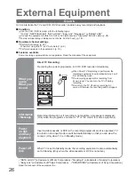
Page 26: ...or SMARTLINK Connect the equipment to this TV s AV2 or AV3 terminal via a fully wired SCART cable p 28 Q Link terminal setup in Setup menu Q Link AV2 AV3 out p 16 Q Link Direct TV Recording Recording...

Page 27: ...omatically When it is stopped operating input mode is returned Power on link When the connected Panasonic equipment is operated TV is also automatically turned on and the content is reproduced Only wh...

Page 28: ...Y PB PR AUDIO PC Y PB PR L R R L V S V R L V S V 28 Connections Connect VCR DVD recorder Recording Playback Connect DVD player Playback Connect Set top box RGB input Rear of the TV Rear of the TV Fro...

Page 29: ...ect DVD recorder and VCR example Easy playback For connection to HDMI2 terminal refer to p 30 Rear of the TV Rear of the TV Rear of the TV This TV Panasonic Player theatre Panasonic DVD recorder DIGA...

Page 30: ...ther connections consult the instructions of each equipment the table below and the speci cations p 39 Types of connectable equipment to each connector Connections overview External Equipment VIDEO or...

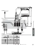
Page 31: ...VIDEO S VIDEO S VIDEO COMPONENT L R L R Y PB PR AUDIO PC 31 Recommended Connection Listening Set top box DVD Recorder VCR SCART cable RF cable or Q Link SCART cable Q Link To watch satellite broadcast...

Page 32: ...iewed is a widescreen picture If Auto aspect detects a widescreen signal it switches into the appropriate 16 9 or 14 9 widescreen mode If Auto aspect does not detect a widescreen signal then this adva...

Page 33: ...d by connecting the TV and the equipment HDMI compatible equipment 1 with an HDMI or DVI output terminal such as a set top box or a DVD player can be connected to the HDMI terminal using an HDMI compl...

Page 34: ...B VIDEO S VIDEO Q Link AV3 Pins 15 and 20 are dependent on AV3 S VHS VIDEO switching Hot Plug Detect DDC CEC Ground SCL CEC TMDS Clock Shield TMDS Data0 TMDS Data0 TMDS Data1 Shield TMDS Data2 TMDS Da...

Page 35: ...Memory cards must be formatted with FAT12 or FAT16 in order to be viewed on TV If the card is not formatted it may cause incompatibility with certain memory card adapters If this happens reformat the...

Page 36: ...echnology giving you ne picture details Occasionally a few non active pixels may appear on the screen as a xed point of red green blue or black Please note this does not affect the performance of your...

Page 37: ...g of the connected equipment to 2ch L PCM Check the HDMI1 input setting in the Sound menu p 16 If digital sound connection has a problem select analogue sound connection p 33 Sound level is low or sou...

Page 38: ...nlock to operate Unlock the SD card This le is locked Please unlock to operate Unlock the le in the card This type of format is not supported The TV does not support the format For the applicable form...

Page 39: ...R Aerial Rear VHF UHF Operating Conditions Temperature 0 C 35 C Connection Terminals AV1 Scart terminal 21 Pin terminal Audio Video in Audio Video out RGB in AV2 Scart terminal 21 Pin terminal Audio V...

Page 40: ...This symbol is only valid in the European Union If you wish to discard this product please contact your local authorities or dealer and ask for the correct method of disposal Printed in Czech Republic...

Reviews: