5
3 Service Navigation
3.1.
Service Hint
Board Name
Function
Board Name
Function
P
Power Supply
C1
Data Driver (Upper Right)
A
DC-DC Converter
Speaker out, Sound Processor
AV Terminal, AV Switch, Ethernet LAN
Digital Signal Processor, Micom, HDMI Interface
Peaks PRO, GC6
C2
Data Driver (Upper Center)
C3
Data Driver (Upper Left)
C4
Data Driver (Lower Left)
C5
Data Driver (Lower Center)
C6
Data Driver (Lower Right)
D
Format Converter, Plasma AI, Sub-Field Processor
SC
Scan Drive
K
Remote receiver, Power LED
SU
Scan out (Upper)
S
Power Switch
SD
Scan out (Lower)
GS
SD Card Slot
SS
Sustain Drive
GL
SD Blue LED
SS2
Sustain connector (Upper)
GH
HDMI4 in
SS3
Sustain connector (Lower)
G
Front Terminal, Key Switch
PA
Fan control
HC
PC in, Audio out
Summary of Contents for Viera TH-65PY800P
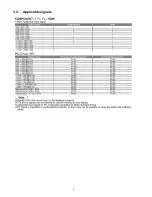
Page 6: ...6 3 2 Applicable signals ...
Page 16: ...16 6 4 No Picture ...
Page 32: ...32 8 1 4 Adjustment Volume Location 8 1 5 Test Point Location ...
Page 40: ...40 ...
Page 42: ...42 10 3 Wiring 2 ...
Page 43: ...43 10 4 Wiring 3 ...
Page 44: ...44 ...
Page 45: ...45 11 Schematic Diagram 11 1 Schematic Diagram Note ...
Page 132: ...132 13 1 2 Fan and Flat cable location ...
Page 133: ...133 13 1 3 Packing ...
Page 134: ...134 13 1 4 Mechanical Replacement Parts List ...
Page 139: ...139 13 2 Electrical Replacement Parts List 13 2 1 Replacement Parts List Notes ...


