21
7.8.
Remove the FFC Shield Metal
(A) and remove the Core
Holder (A)
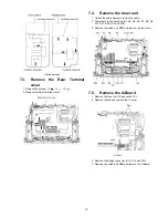
1. Unlock the cable clamper to free the cable.
2. Remove the screws (
×
4
) and remove the FFC Shield
Metal (A).
3. Remove the screws (
×
3
) and remove the Core Holder
(A).
7.9.
Remove the FFC Shield Metal
(B) and remove the Core
Holder (B)
1. Remove the screws (
×
2
) and remove the A-Board unit
support metal.
2. Remove the screws (
×
4
) and remove the FFC Shield
Metal (B).
3. Remove the screws (
×
4
) and remove the Core Holder
(B).
7.10. Remove the D-Board
1. Remove the Tuner unit. (See section 7.4.)
2. Disconnect the connectors (D3, D5 and D25).
3. Disconnect the flexible cables (D20, D31, D32, D33, D34,
D35 and D36).
4. Remove the screws (
×
4
) and remove the D-Board.
7.11. Remove the PA-Board
1. Disconnect the connectors (PA5, PA6, PA8, PA33, PA35,
PA36 and PA37).
2. Remove the screws (
×
2 ).
3. Remove the PA-Board.
Summary of Contents for Viera TH-65PY800P
Page 6: ...6 3 2 Applicable signals ...
Page 16: ...16 6 4 No Picture ...
Page 32: ...32 8 1 4 Adjustment Volume Location 8 1 5 Test Point Location ...
Page 40: ...40 ...
Page 42: ...42 10 3 Wiring 2 ...
Page 43: ...43 10 4 Wiring 3 ...
Page 44: ...44 ...
Page 45: ...45 11 Schematic Diagram 11 1 Schematic Diagram Note ...
Page 132: ...132 13 1 2 Fan and Flat cable location ...
Page 133: ...133 13 1 3 Packing ...
Page 134: ...134 13 1 4 Mechanical Replacement Parts List ...
Page 139: ...139 13 2 Electrical Replacement Parts List 13 2 1 Replacement Parts List Notes ...

