131
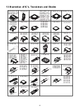
13 Illustration of IC’s, Transistors and Diodes
No.1
No.1
MIP2F20MSSCF
MIP2F50MSSCF
1
4
5
2
3
C0JBAZ001466 (20P)
C3ABMG000238 (50P)
C3EBEC000047 (8P)
C2BBCC000007 (16P)
C0FBZK000013 (64P)
C2HBCY000030 (128P)
C0HBB0000057 (44P)
C1AB00002975 (100P)
C1BB00001134 (56P)
C1AB00002977 (80P)
RFKWMZT2PPK1 (100P)
C0ABBB000230
C0ABBB000038
C0AABB000085
C0ABBB000125
C3EBEC000060
C0DBEKG00004
C1AB00002989 (144P)
C0DBAYH00005
C0CBCBG00013
C0CBCAG00015
C0CBACC00046
C0CBADC00042
RFKB4528AA-M
C0DAEMZ00001
1
3
2
B1BABK000001
B1ABCF000176
B1ADCE000012
B1ABCF000011
B1GBCFGN0018
B1ABCF000079
B1GDCFGG0005
2SA207700L
B1ADNB000003
UNR221300L
B1ADCF000001
B1GBCFJA0017
B1GBCFGG0030
B1ADMB000003
B1HBDCA00001
4
6
B0BC026A0007
B0ACCK000005
B0JCMD000010
B0JCAE000001
Cathode
Anode
A
Ca
A
Ca
Cathode
Cathode
Anode
Anode
Anode
B0EAMM000057
B0HAMP000094
B0JAME000029
B0JAMF000011
B0HBSM000054
B0EDKT000009
Ca
A
A
Ca
A
A
MAZ8200GML
MAZ8300GML
MAZ8075GML
MAZ8120GML
MAZ8150GML
MAZ8051GML
C0EBE0000338
C0ZBZ0001675
C0JBAR000396
C0JBAB000986
C0CBCDC00014
C0CBCBC00049
C0EBG0000107
B0JCPG000005
B0HCMM000019
Cathode
Anode
A
Ca
2SC3940ARA
B1GDCFJJ0008
B1GBCFJJ0007
E
B
C
2SB0621AHA
No.1
RFKWMZT2PPK2 (100P)
1
1
12
13
24
25
36
37
48
30
31
50
51
80
81
100
C0DAAMH00015
1
7
B0BC019A0007
B0BC6R100010
B0BC02400011
B0BC4R600016
B0BC035A0007
Cathode
Anode
A
Ca
B0EBNR000015
Anode
Anode
Anode
Cathode
B3AEA0000058
A
Ca
Cathode
Anode
UNR5111J0L
B0HDRM000002
Ca
A
A
MA2J1110GL
B3AJA0000011
B1CBRK000001
1 2 3
4 5
Summary of Contents for VIERA Link SB-ZT2EE
Page 10: ...10 5 Location of Controls and Components 5 1 Main Unit SU ZT2 ...
Page 11: ...11 5 2 Speaker Unit SB ZT2 5 3 Remote Control ...
Page 12: ...12 6 Installation ...
Page 13: ...13 6 1 Basic Connections 6 1 1 Connecting equipment with HDMI terminal TV DVD recorder etc ...
Page 14: ...14 6 1 2 Connecting equipment without HDMI terminal DVD player VCR etc ...
Page 15: ...15 6 1 3 Connecting STB etc and audio terminals DVD player etc ...
Page 16: ...16 6 1 4 Other connections ...
Page 17: ...17 6 2 AC power supply connection ...
Page 18: ...18 7 Speaker setting SB ZT2 7 1 Setting the speakers Front and Surround speakers ...
Page 19: ...19 ...
Page 20: ...20 7 2 Setting surround speakers ...
Page 28: ...28 9 2 2 Speaker Unit SB ZT2 ...
Page 29: ...29 9 2 3 Speaker Unit SB ZT2 Wireless Link ...
Page 30: ...30 ...
Page 32: ...32 ...
Page 33: ...33 10 1 Main Parts Location Diagram 10 1 1 Main Unit SU ZT2 ...
Page 34: ...34 10 1 2 Speaker Unit SB ZT2 ...
Page 36: ...36 10 2 2 Speaker Unit SB ZT2 ...
Page 49: ...49 Step 4 Remove the Weight ...
Page 50: ...50 Step 5 Remove 10 screws ...
Page 54: ...54 Step 11 Remove 2 screws Step 12 Lift up to remove Arm Cover A ...
Page 56: ...56 Step 14 Tilt the Woofer Block in order as arrows shown to detach it from the Tweeter Block ...
Page 67: ...67 Step 3 Remove the heatsink with the IC5701 ...
Page 68: ...68 Step 4 Remove 1 screw Step 5 Remove IC5701 from the heatsink ...
Page 70: ...70 Step 4 Place the heatsink with the IC5701 onto the SMPS P C B ...
Page 82: ...82 Step 4 Remove 3 screws Step 5 Remove the Power Button ...
Page 87: ...87 Step 3 Remove 4 screws Step 4 Lift up to remove Woofer Speaker SP1 ...
Page 111: ...111 Step 11 Remove 3 screws ...
Page 112: ...112 Step 12 Remove the Light Panel Step 13 Remove the Power Button ...
Page 113: ...113 Step 14 Hold on to the P C B Holder and lift up the Input P C B as arrow shown ...
Page 114: ...114 Step 15 Place the D Amp P C B and Input P C B on an insulation sheet ...
Page 132: ...132 ...
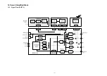
Page 133: ...133 14 Overall Simplified Block 14 1 Signal Flow SU ZT2 ...
Page 144: ...144 ...
Page 148: ...148 ...
Page 168: ...168 ...
Page 176: ...176 ...
Page 178: ...178 ...
Page 182: ...182 ...

