background image

42

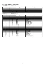
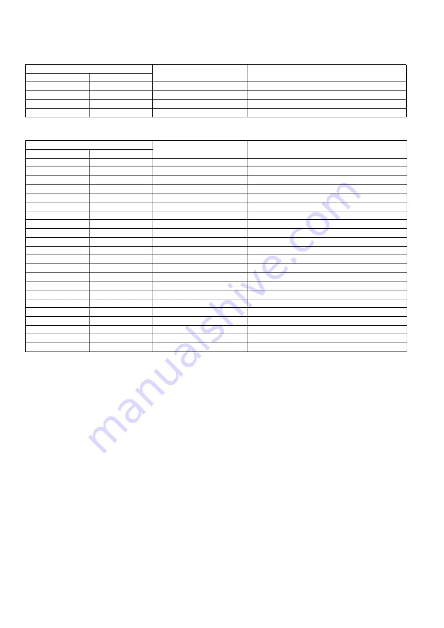
10.3. Explanation of Connector

JK1 [CONTROL Board] - USB Peripheral

Pin No.

Signal Name

Description

JK1

USB

1

1

VBUS

VBUS Signal

2

2

D-

D- Signal

3

3

D+

D+ Signal

4

4

GND

Ground

CN2 [CONTROL Board] - CN300 [RELAY Board]

Pin No.

Signal Name

Description

CN2

CN300

1

22

LEDKR

LED Cathode

2

21

LEDAR

LED Anode

3

20

3.3V-S

Switched 3.3V

4

19

CLKR

CCD CLK

5

18

GND

Ground

6

17

RSTR

CCD Read Strobe

7

16

RD2R

CCD Read2 Select

8

15

RD1R

CCD Read1 Select

9

14

ADRR[0]

CCD Address 0

10

13

ADRR[1]

CCD Address 1

11

12

ADRR[2]

CCD Address 2

12

11

ADRR[3]

CCD Address 3

13

10

ADRR[4]

CCD Address 4

14

9

ADRR[5]

CCD Address 5

15

8

ADRR[6]

CCD Address 6

16

7

ADRR[7]

CCD Address 7

17

6

HDR

CCD Direction

18

5

GND

Ground

19

4

HCLKR

Horizontal CLK

20

3

3.3V-S

Switched 3.3V

21

2

ADINRP

CCD ANALOG INPUT+

22

1

ADINRN

CCD ANALOG INPUT-

Summary of Contents for UB-T580

Page 1: ...sonic System Networks Co Ltd 2012 Unauthorized copying and distribution is a violation of law Order Number KM71201706CE Category Number H19 Electronic Board elite Panaboard Model No UB T580 Model No UB T580W ...

Page 2: ...naboard from Its Packaging 17 4 6 Assembling the elite Panaboard 18 4 7 Confirming the elite Panaboard Operation 27 4 8 Repackaging 27 5 SECTIONAL VIEW 28 6 SCREEN OPERATION 29 6 1 Position Detection Mechanism 29 7 MAINTENANCE 30 7 1 Maintenance Table 30 7 2 Cleaning the elite Panaboard 30 8 DISASSEMBLY INSTRUCTIONS 31 8 1 Disassembly Flowchart 31 8 2 Exterior 32 8 3 Boards 35 9 TROUBLESHOOTING 38...

Page 3: ...s neither the products nor its parts or components shall be modified 2 If cable assembly is supplied as the smallest unit when servicing make sure to replace the cable assembly 1 3 For Service Technicians ICs and LSIs are vulnerable to static electricity When repairing the following precautions will help to prevent recurring malfunctions 1 Cover the plastic parts with aluminum foil 2 Ground the so...

Page 4: ...y flow onto the opposite side See figure below 1 4 1 Suggested Pb free solder We recommend you to use the following solder when re soldering components for repair Before using other Pb free solder than the following solder make sure to confirm that the solder maker you use has the license agreement for Pb free solder Supplier Senju Metal Industry Co Ltd http www senju m co jp Part Description in S...

Page 5: ...ach area country This difference can be distinguished by the Areas Countries Distinction Mark printed on the name plate In this manual the Areas Countries Distinction Mark is used to distinguish this difference When servicing repairing or handling this model check the Areas Countries Distinction Mark and use this service manual ...

Page 6: ...b Operating Environment Ambient Temperature 10 C to 35 C 50 F to 95 F Humidity 30 to 80 RH Storage Environment Ambient Temperature 20 C to 60 C 4 F to 140 F Humidity 20 to 80 RH PC Interface 2 USB 2 0 Full Speed Input Unit Screen Board Size Height x Width 1 175 mm x 1 582 mm 3 ft 10 26 in x 5 ft 2 29 in Interactive Features Effective Area A x B Height x Width 1 175 mm x 1 567 mm 3 ft 10 26 in x 5f...

Page 7: ...t Ambient Temperature 20 C to 60 C 4 F to 140 F Humidity 20 to 80 RH PC Interface 4 USB 2 0 Full Speed Input Unit Screen Board Size Height x Width 1 175 mm x 1 860 mm 3 ft 10 26 in x 6 ft 1 23 in Interactive Features Effective Area A x B Height x Width Depending on the condition of the display aspect ratio specified by a PC the effective area is different as follows Case1 Aspect Ratio 9 16 1 037 m...

Page 8: ... 6 Options Accessories and Supplies Model No Description Remarks KX B061 Stand Optional Stand UE 608020 Electronic Pen UE 608021 Stylus Pen UE 608030 Up Down Unit UE 608031 Stand Table Unit UE 608032 Short Throw Arm Unit UG 6020 Penpoint Used for Electronic Pen ...

Page 9: ...9 2 7 Exterior Dimensions 2 7 1 UB T580 2 7 1 1 When mounting using the wall mounting plates 2 7 1 2 When mounting using a Stand sold separately KX B061 ...

Page 10: ...10 2 7 2 UB T580W 2 7 2 1 When mounting using the wall mounting plates 2 7 2 2 When mounting using a Stand sold separately KX B061 ...

Page 11: ...11 3 COMPONENT IDENTIFICATION 3 1 Main Unit ...

Page 12: ...12 3 2 Stylus Pen ...

Page 13: ...r grease such as manufacturing plants or kitchens places with special environments such as those with combustible atmospheres Seaborne or coastal places and places where corrosive gases are given off Places where the operating temperature range of the electronic board temperature 10 C to 35 C 50 F to 95 F humidity 30 to 80 will be exceeded 2 To prevent deformation and discoloring avoid installing ...

Page 14: ...14 4 3 Included Accessories Confirm that the following items are included with the elite Panaboard ...

Page 15: ...chor bolts are used when installing the elite Panaboard on the wall Specified pull out strength 784 N 80 kgf 4 4 3 Checkpoints to be Observed While Working 4 4 3 1 Work related Safety Precautions Before mounting the electronic board read through the following points and take care to avoid accidents 1 To ensure that the work is accomplished safely and properly make it a basic rule to strictly obser...

Page 16: ...e anchors and check that they have been tightened up securely Note Recommended tightening torque 5 2 N m 53 kgf cm 1 Using the measuring tape and level mark the 8 locations to insert the screws 2 Drill 8 holes for the wall mounting plates Drill holes that are appropriate for the anchors you are using Use a dust pump to clean the holes after drilling to make sure no scraps remain inside the holes 3...

Page 17: ...17 4 5 Unpacking the elite Panaboard from Its Packaging ...

Page 18: ...mbling the elite Panaboard 4 6 1 For Wall Mounting 1 With the Cable Holders and Screws 3 each No 6 fasten the USB Cable to wire the cable along the outer side of the elite Panaboard clock wise or counterclockwise ...

Page 19: ...4 to the 2 locations Note The attachment positions can be chosen from the 4 locations as required 3 Remove the 2 screws that secure the 2 Plate Covers Then while holding each of the Plate Cover attach the 2 screws to the lower holes to secure the covers ...

Page 20: ... position on both sides as illustrated so that elite Panaboard can be hung onto the Wall Mounting Plates on the wall Note Tightening Torque More than 1 2 N cm 12 kgf cm 5 Remove the 5 screws to release the Upper Cover from the Panaboard ...

Page 21: ...21 6 Hang the elite Panaboard onto the Wall Mounting Plates No 2 No 3 on the wall 7 With the M6 Bolts Spring Washers 4 each WS2 and 4 Flash Washers No 11 secure the elite Panaboard to the wall ...

Page 22: ...lite Panaboard can operate See 4 7 Confirming the elite Panaboard Operation 10 Unplug the USB Cable from the PC to turn off the power 11 Attach the Cable Clamp 7 to the left or right side of the Screen Plate Back 12 Bundle the USB Cable with the clamp 7 ...

Page 23: ...23 13 Wipe the screen board surface Gently wipe the screen board surface with a soft moist cloth ...

Page 24: ...le to wire the cable along the outer side of the elite Panaboard See 4 6 1 1 3 Attach the 2 Pen Holders No 4 to the 2 locations See 4 6 1 2 4 As required relocate the screw attachment position on both sides as illustrated so that the position where the elite Panaboard is hung can be changed Note Tightening Torque More than 1 2 N cm 12 kgf cm ...

Page 25: ...ew heads 6 Secure the elite Panaboard to the Stand Frame using the 2 wing bolts included with the Stand 7 Confirm that the elite Panaboard can operate See 4 7 Confirming the elite Panaboard Operation 8 Unplug the USB Cable from the PC to turn off the power ...

Page 26: ...26 9 Attach the Cable Clamp 7 to the left or right side of the Screen Plate Back 10 Bundle the USB Cable with the clamp 7 11 Wipe the screen board surface See 4 6 1 13 ...

Page 27: ...ing detected If other fingers are detected the position may get shifted After you touch an indicated point correctly the next point is shown automatically When calibration has finished normally a completion dialog box is displayed 4 Confirm operation by writing on the screen board with the stylus pen or a finger and checking that the writing is displayed on the computer s screen Your writing with ...

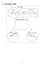
Page 28: ...28 5 SECTIONAL VIEW ...

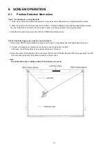
Page 29: ...at the light is scanned by the CCD that CMOS Camera Module has Case 2 Obstacle finger or pen top is on an optical path 1 LEDs which CMOS Camera Module located on both sides of screenboard has emit light toward the screen 2 The light is blocked by an obstacle and so the light does not go back to the CCD In this case the CCD waveform has any partial depression of the level 3 By monitoring the CCD wa...

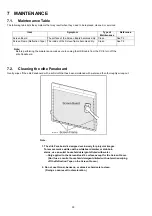
Page 30: ...signed exclusively for projector images To remove marks written with a whiteboard marker or stubborn stains use a neutral household detergent diluted with water Only applied to the Screen Board s surface except for the Screen Frame Don t use a neutral household detergent diluted with water when wiping off the Reflection Tape on the Screen Frame 2 Do not use thinner benzene or abrasive chemicals to...

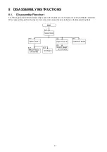
Page 31: ...mbly Flowchart The following flowcharts indicate disassembly sequence for the Exterior Unit Components and Circuit Board assemblies When reassembling perform the steps in the reverse order unless otherwise instructed in the Reassembling Notes ...

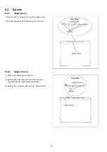
Page 32: ...screws on the top of the Upper Cover 2 Pull the Upper Cover forward to remove the cover 1 Remove the Upper Cover See 8 2 1 2 Demount the elite Panaboard unit from the wall Available only for wall mounting installation 3 Remove the 3 screws on the top of the Upper Cover L ...

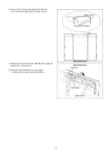
Page 33: ...from the back Then pull forward and remove the Upper Cover L 5 Disconnect the connector to the LED Board to release the Upper Cover L from the unit 6 Mount the elite Panaboard to the wall again Available only for wall mounting installation ...

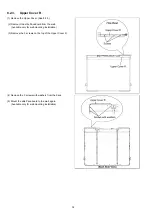
Page 34: ...e elite Panaboard from the wall Available only for wall mounting installation 3 Remove the 3 screws on the top of the Upper Cover R 4 Remove the 3 screws with washers from the back 5 Mount the elite Panaboard to the wall again Available only for wall mounting installation ...

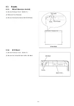
Page 35: ...d on the left 8 3 2 LED Board 1 Remove the Upper Cover L See 8 2 2 2 Disconnect the 2 flat cables 3 Remove the screw that secures the RELAY Board 1 Remove the Upper Cover L See 8 2 2 2 Remove the 2 screws that secures the LED Board ...

Page 36: ...36 8 3 3 RELAY Board on the right 1 Remove the Upper Cover R See 8 2 3 2 Disconnect the 2 flat cables 3 Remove the screw that secures the RELAY Board ...

Page 37: ...ROL Board 1 Remove the Upper Cover See 8 2 1 2 Pull and remove the CONTROL Board s Cover 3 Disconnect the 4 connectors 2 flat cable 1 cable to LED Board USB cable 4 Remove the 3 screws that secure the CONTROL Board ...

Page 38: ...econds or more plug the USB cable again without touching the screen surface The reflection tape attached inside the screen frame becomes dirty 1 Clean the reflection tape around the screen frame 2 Replace the tape with a new one 3 Restart the elite Panaboard Then check that the LED turns green The reflection tape is peeled from the inside of the screen frame 1 Replace the tape with a new one 2 Res...

Page 39: ...the USB cable CONTROL Board has a failure 1 Replace the elite Panaboard 2 elite Panaboard was disconnected The connection between elite Panaboard and PC is not proper 1 Check the connection between the elite Panaboard and PC 2 Plug the USB cable to another USB interface on the PC The USB cable from the elite Panaboard is connected to PC via a USB Hub 1 Plug the USB Cable to the PC directly The USB...

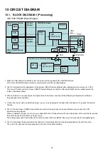
Page 40: ...d not to go back the default position 5 The CCD in the Sensor CMOS Camera Module will continuously trace the above information to produce the CCD waveform analog signal When an obstacle a finger or pen is on an optical path the CCD waveform will have a depression of the level that is required to specify the position touched by a finger or pen The analog signal will be transmitted to the A D Conver...

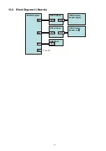
Page 41: ...41 10 2 Block Diagram 2 Boards RELAY Board CMOS Camera Module Right CONTROL Board LED Board CN301 CN300 CN2 RELAY Board CMOS Camera Module Left䋩 CN301 CN300 CN3 CN200 CN4 JK1 From PC ...

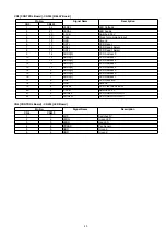
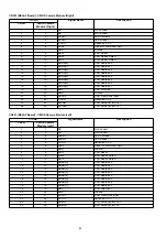
Page 42: ...0 3 3V S Switched 3 3V 4 19 CLKR CCD CLK 5 18 GND Ground 6 17 RSTR CCD Read Strobe 7 16 RD2R CCD Read2 Select 8 15 RD1R CCD Read1 Select 9 14 ADRR 0 CCD Address 0 10 13 ADRR 1 CCD Address 1 11 12 ADRR 2 CCD Address 2 12 11 ADRR 3 CCD Address 3 13 10 ADRR 4 CCD Address 4 14 9 ADRR 5 CCD Address 5 15 8 ADRR 6 CCD Address 6 16 7 ADRR 7 CCD Address 7 17 6 HDR CCD Direction 18 5 GND Ground 19 4 HCLKR H...

Page 43: ...1 CCD Address 1 11 12 ADRR 2 CCD Address 2 12 11 ADRR 3 CCD Address 3 13 10 ADRR 4 CCD Address 4 14 9 ADRR 5 CCD Address 5 15 8 ADRR 6 CCD Address 6 16 7 ADRR 7 CCD Address 7 17 6 HDL CCD Direction 18 5 GND Ground 19 4 HCLKL CCD Pixel clock input 20 3 3 3V S Switched 3 3 V 21 2 ADINLP CCD ANALOG INPUT 22 1 ADINLN CCD ANALOG INPUT CN4 CONTROL Board CN200 LED Board Pin No Signal Name Description CN4...

Page 44: ...xel clock input 22 22 3 3V S Switched 3 3 V 23 23 ADINLP CCD ANALOG INPUT 24 24 ADINLN CCD ANALOG INPUT CN301 RELAY Board CMOS Camera Module Left Pin No Signal Name Description CN301 CMOS Camera Module Left 1 1 NC No Connect 2 2 NC No Connect 3 3 LEDKL LED Cathode 4 4 LEDAL LED Anode 5 5 3 3V S Switched 3 3 V 6 6 CLKL Clock for command input 7 7 GND Ground 8 8 RSTL CCD Reset 9 9 RD2L CCD Read2 Sel...

Page 45: ...45 11 SCHEMATIC DIAGRAM Index 11 1 RELAY Board 11 2 LED Board Note The schematic diagrams are the latest at the time when this service manual is issued but are subject to change without notice ...

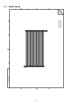
Page 46: ...MN22BA0109 CN300 1 2 3 4 5 6 7 8 9 10 11 12 13 14 15 16 17 18 19 20 21 22 C B A D 3 2 4 5 B C D A 6 RELAY Board K1MN24BA0112 CN301 1 2 3 4 5 6 7 8 9 10 11 12 13 14 15 16 17 18 19 20 21 22 23 24 1 1 RELAY Board UB T580 T580W ...

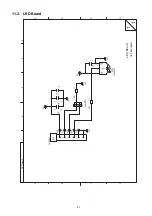
Page 47: ...D K1KA06BA0014 CN200 1 2 3 4 5 6 25 10u C200 25 10u C201 0 1u C202 0 1u C204 270 R201 GND R G B3AGA0000063 D200 1 2 3 CL200 CL201 CL202 CL203 CL204 C B A D 3 2 4 5 B C D A 6 LED Board B3RAB0000099 RM200 VCC 3 VOUT 1 GND 2 1 1 LED Board UB T580 T580W ...

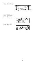
Page 48: ...48 12 CIRCUIT BOARDS Index 12 1 RELAY Board 12 2 LED Board ...

Page 49: ... Front Side 12 2 2 Back Side PNLB2086ZB WK PNLPUBT580QMM B 94V 0 RELAY to CCM to Control PbF CN300 CN301 1 22 1 24 PNLB2086ZB WK PNLPUBT580QMM C 94V 0 LED CN200 PbF D200 RM200 1 6 1 3 C200 C201 C202 C204 CL200 CL201 CL202 CL203 CL204 R200 R201 ...

Page 50: ...50 13 PARTS LOCATION AND MECHANICAL PARTS LIST ...

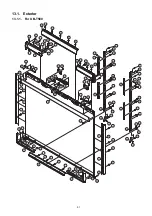
Page 51: ... 21 21 21 28 28 21 21 21 21 21 21 21 21 21 21 21 21 21 21 35 35 21 21 21 17 30 20 25 29 29 29 29 29 29 27 27 25 26 26 25 25 11 12 24 10 500 300 300 400 400 300 300 400 400 400 302 302 400 401 401 401 401 401 400 400 300 22 300 22 300 300 300 300 300 300 300 300 300 300 300 300 300 301 301 300 300 300 300 300 500 400 400 15 ...

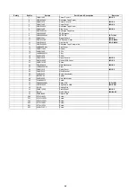
Page 52: ...ront Cover 15 PNHG1164Z Rubber 16 PNJE1126Z FFC L 17 J0KD00000151 Filter 18 PNJE1127Z FFC R 19 PNKV1153Z Upper Cover R ISO PS 20 PNGE1022Z Control PCB Cover ISO PS 21 PNHD1018Z Screw 22 PNGE1021Z Hold Plate Cover ISO PS 23 J0KE00000138 Filter 24 PNKV1151Z Upper Cover ISO PS 25 PNUF1023Z Hook Bracket 26 PNUF1020Z Board Attachment 27 MWSP5 50 Spacer 28 PNUF1022Z Hold Plate Lower 29 PJNAC0031Z Screw ...

Page 53: ...53 13 1 2 For UB T580W To be continued later ...

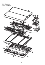
Page 54: ...54 13 2 Packing 13 2 1 For UB T580 S1 S2 S3 S4 S4 S6 S6 S4 S4 S6 S6 S5 S5 S8 34 S9 S7 S7 S10 S14 S15 S11 S16 S17 S12 400 S13 ...

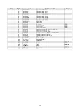
Page 55: ...NPN1249Z Top Center Cushion ISO PS S6 PNPN1250Z Bottom Cushion ISO PS S7 PNPN1251Z Bottom Center Cushion ISO PS S8 PNQX5369Z Installation Manual for UB T580 C U G A SX AG S8 PNQX5370Z Installation Manual for UB T580 T S8 PNQX5374Z Installation Manual for UB T580 BR S9 PNQX5377Z Operating Instructions for UB T580 C U G A SX AG S9 PNQX5378Z Operating Instructions for UB T580 T S9 PNQX5380Z Operating...

Page 56: ...56 13 2 2 For UB T580W To be continued later ...

Page 57: ...57 14 REPLACEMENT PARTS LIST ...

Page 58: ... CN301 K1MN24BA0112 Connector Safety Ref No Part No Part Name Description Remarks C200 F1K1E1060004 10 C201 F1K1E1060004 10 C202 ECUV1H104ZFV 0 1 C204 ECUV1H104ZFV 0 1 CN200 K1KA06BA0014 Connector D200 B3AGA0000063 Diode R200 ERJ3GEYJ271 270 R201 ERJ3GEYJ271 270 RM200 B3RAB0000099 Photo Detector PNHR1626Z IR Spacer ...

Reviews: