


YE
S
M
a
ke nece
ssa
ry correction
s
.
Check the
a
l
a
rm
content
s
.
Check the
a
l
a
rm content
s
.
T
u
rn OFF the indoor
a
nd
o
u
tdoor
u
nit power
NO
*
2
*3
*3
*
2
CA
S
E 1
CA
S
E 2
CA
S
E
3
B CA
S
E
3
A
YE
S
YE
S
NO
YE
S
NO
NO
NO
YE
S
YE
S
NO
Recheck the item
s
to check
b
efore the te
s
t r
u
n.
Are the inter-
u
nit control wire
s
connected to more th
a
n 1 refriger
a
nt
s
y
s
tem?
I
s
it po
ss
i
b
le to t
u
rn ON the power only
for the 1 refriger
a
nt
s
y
s
tem where the
te
s
t r
u
n will
b
e performed?
Will
au
tom
a
tic
a
ddre
ss
s
etting
b
e
performed in He
a
ting mode?
I
s
it OK to
s
t
a
rt the compre
ss
or
s
?
T
u
rn ON the indoor
a
nd
o
u
tdoor
u
nit powe r .
S
hort-circ
u
it the mode ch
a
nge pin
(CN50) on the o
u
tdoor m
a
in
u
nit PCB.
At the
sa
me time,
s
hort-circ
u
it the
au
tom
a
tic
a
ddre
ss
pin (CN51) for 1
s
econd or longe r , then p
u
ll it o
u
t .
S
hort-circ
u
it the
au
tom
a
tic
a
ddre
ss
pin (CN51) on the o
u
tdoor
u
nit PCB
for 1
s
econd or longe r ,
then rele
as
e it.
S
hort-circ
u
it the
au
tom
a
tic
a
ddre
ss
pin (CN51)
on the o
u
tdoor
u
nit PCB for 1
s
econd or longe r ,
then rele
as
e it.
S
t
a
rt indoor
a
nd o
u
tdoor
u
nit
cooling oper
a
tion.
LED 1
a
nd 2
b
link
a
ltern
a
tel y .
S
t
a
rt indoor
a
nd o
u
tdoor
u
nit
he
a
ting oper
a
tion.
LED 1
a
nd 2
b
link
a
ltern
a
tel y .
LED 1
a
nd 2
b
link
a
ltern
a
tely
(
ab
o
u
t 2 or
3
min
u
te
s
).
I
s
it OK to
s
t
a
rt the compre
ss
or
s
?
T
u
rn ON the indoor
a
nd
o
u
tdoor
u
nit powe r .
T
u
rn OFF the indoor
a
nd o
u
tdoor
u
nit
T
u
rn ON the indoor
a
nd
o
u
tdoor
u
nit power for th
a
t
refriger
a
nt
s
y
s
tem onl y .
Are LED
s
1
a
nd 2 on the
o
u
tdoor
u
nit PCB OFF?
Are LED
s
1
a
nd 2 on the
o
u
tdoor
u
nit PCB OFF?
S
et the No. of indoor
u
nit
s
.
S
et the
s
y
s
tem
a
ddre
ss
.
When m
u
ltiple o
u
tdoor
u
nit
s
exi
s
t, di
s
connect the termin
a
l
s
extended from the
s
horted pl
u
g
s
(CN
33
)
a
t
a
ll o
u
tdoor m
a
in
u
nit
PCB
s
except for 1.
Altern
a
tivel y , move the
s
ocket
s
to the OPEN
s
ide .
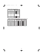
<O
u
tdoor
u
nit control PCB>
Unit No.
s
etting
s
witch
(
S
004)
<O
u
tdoor
u
nit control PCB>
Unit No.
s
etting
s
witch
(
S
002
a
nd
S
00
3
)
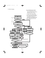
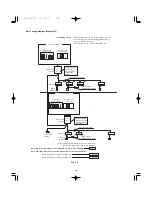
Refer to Fig. 7-4
(Check the link wiring.)
Refer to
“
T
ab
le of
S
elf-Di
a
gno
s
tic F
u
nction
s
a
nd
De
s
cription of Al
a
rm Di
s
pl
a
y
s
.
”
*
2
A minim
u
m of 5 ho
u
r
s
m
us
t h
a
ve p
ass
ed
a
fter the
power w
as
t
u
rned ON to the o
u
tdoor
u
nit.
*3
All indoor
u
nit
s
oper
a
te in
a
ll refriger
a
nt
s
y
s
tem
s
where the power i
s
ON.
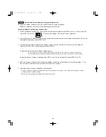
Check th
a
t te
s
t r
u
n prep
a
r
a
tion i
s
OK.
(Do not
a
llow the
s
hort-circ
u
ited pin
s
to rem
a
in
s
hort-circ
u
ited.)
Refer to the Remote
Controller te
s
t-r
u
n
s
etting
s
.
S
et the Wired Remote Controller for te
s
t r
u
n.
Doe
s
s
y
s
tem oper
a
te?
Ret
u
rn Remote Controller to norm
a
l mode
Check
a
nd m
a
ke correction
s
a
ccording to
“
T
ab
le of
S
elf-Di
a
gno
s
tic F
u
nction
s
.
”
End te
s
t r
u
n.
M
a
ke nece
ssa
ry
correction
s
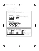
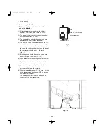
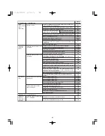
7-2. Test Run Procedure
Items to Check Before the Test Run
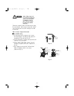
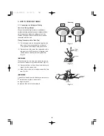
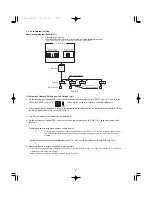
1. Turn the remote power switch on at
least 5 hours before the test, in order to
energize the crankcase heater.
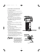
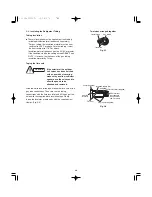
2. Turn the outdoor service valves (2
locations) to the full-open positions.
●
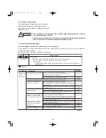
Use caution when making the settings. If
there are duplicated system addresses,
or if the settings for the Nos. of the
indoor units are not consistent, an alarm
will occur and the system will not start.
●
These settings are not made on the
indoor unit PCB.
Fig. 7-3
34
Summary of Contents for U-36LE1U6
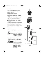
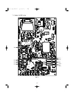
Page 35: ...35 7 3 Outdoor Unit PCB Setting CN51 CN50 D043 LED2 D042 LED1 S003 CN33 S002 S004 Fig 7 4...
Page 46: ...46...
Page 47: ...47...
Page 48: ...DC0811 0 Printed in Japan...


