


27
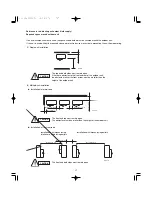
Caution Before Connecting Tubes Tightly
(1) Apply a sealing cap or water-proof tape to prevent dust or
water from entering the tubes before they are used.
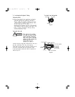
(2) Be sure to apply refrigerant lubricant to the matching
surfaces of the flare and union before connecting them
together. This is effective for reducing gas leaks. (Fig. 5-4)
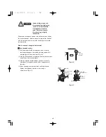
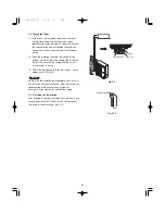
(3) For proper connection, align the union tube and flare tube
straight with each other, then screw in the flare nut lightly
at first to obtain a smooth match. (Fig. 5-5)
●
Adjust the shape of the liquid tube using a tube bender at
the installation site and connect it to the liquid tubing side
valve using a flare.
Cautions During Brazing
●
Replace air inside the tube with nitrogen gas to
prevent copper oxide film from forming during the
brazing process. (Oxygen, carbon dioxide and Freon
are not acceptable.)
●
Do not allow the tubing to get too hot during brazing.
The nitrogen gas inside the tubing may overheat,
causing refrigerant system valves to become dam-
aged. Therefore allow the tubing to cool when brazing.
●
Use a reducing valve for the nitrogen cylinder.
●
Do not use agents intended to prevent the formation
of oxide film. These agents adversely affect the
refrigerant and refrigerant oil, and may cause damage
or malfunctions.
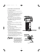
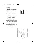
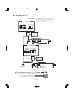
5-2. Connecting Tubing Between Indoor and Outdoor
Units
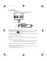
(1) Tightly connect the indoor-side refrigerant tubing extended
from the wall with the outdoor-side tubing.
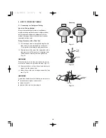
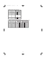
(2) To fasten the flare nuts, apply specified torque as at right:
●
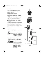
When removing the flare nuts from the tubing connections,
or when tightening them after connecting the tubing, be
sure to use 2 adjustable wrenches or spanners as shown.
(Fig. 5-6)
If the flare nuts are over-tightened, the flare may be dam-
aged, which could result refrigerant leakage and cause in
injury or asphyxiation to room occupants.
●
For the flare nuts at tubing connections, be sure to use the
flare nuts that were supplied with the unit, or else flare nuts
for R410A (type 2). The refrigerant tubing that is used must
be of the correct wall thickness as shown in the table at
right.
Apply refriger
a
nt
l
ub
ric
a
nt
Fig. 5-4
Flare nut
Union
Fig. 5-5
Fig. 5-6
Indoor unit
Outdoor unit
Spanner
Torque wrench
Tube diameter
ø1/4"
(ø6.
3
5 mm)
ø
3
/8"
(ø9.52 mm)
ø1/2"
(ø12.7 mm)
ø5/8"
(ø15.88 mm)
ø
3
/4"
(ø19.05 mm)
Ti
g
htenin
g
torque,
approximate
120 – 160 l
bs
·
in.
(140 – 180 kgf
·
cm)
3
00 –
3
60 l
bs
·
in.
(
3
40 – 420 kgf
·
cm)
4
3
0 – 480 l
bs
·
in.
(490 – 550 kgf
·
cm)
590 – 710 l
bs
·
in.
(680 – 820 kgf
·
cm)
870 – 1040 l
bs
·
in.
(1000 – 1200 kgf
·
cm)
1/
3
2"
(0.8 mm)
1/
3
2"
(0.8 mm)
1/
3
2"
(0.8 mm)
5/128"
(1.0 mm)
over 5/128"
(1.0 mm)
Tube thickne
ss
Because the pressure is approximately 1.6 times
higher than conventional refrigerant pressure, the
use of ordinary flare nuts (type 1) or thin-walled
tubes may result in tube rupture, injury, or
asphyxiation caused by refrigerant leakage.
●
In order to prevent damage to the flare caused by
over-tightening of the flare nuts, use the table
above as a guide when tightening.
●
When tightening the flare nut on the liquid tube,
use an adjustable wrench with a nominal handle
length of 7-7/
8
".
Summary of Contents for U-36LE1U6
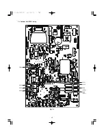
Page 35: ...35 7 3 Outdoor Unit PCB Setting CN51 CN50 D043 LED2 D042 LED1 S003 CN33 S002 S004 Fig 7 4...
Page 46: ...46...
Page 47: ...47...
Page 48: ...DC0811 0 Printed in Japan...


