


31
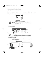
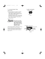
(3) Do a leak test of all joints of the tubing (both indoor and
outdoor) and both gas tube and liquid tube service
valves. Bubbles indicate a leak. Wipe off the soap with a
clean cloth after the leak test.
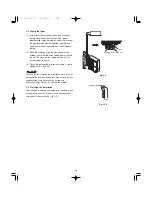
(4) After the system is found to be free of leaks, relieve the
nitrogen pressure by loosening the charge hose
connector at the nitrogen cylinder. When the system
pressure is reduced to normal, disconnect the hose from
the cylinder.
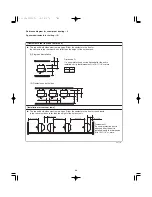
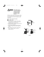
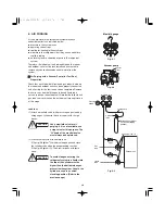
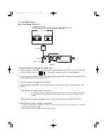
Evacuation
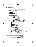
(1) Attach the charge hose end described in the preceding
steps to the vacuum pump to evacuate the tubing and
indoor unit. Confirm that the “Lo” knob of the manifold
valve is open. Then, run the vacuum pump. The
operation time for evacuation varies with the tubing
length and capacity of the pump. The following table
shows the amount of time for evacuation:
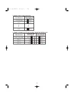
The required time in the above table is calculated based on
the assumption that the ideal (or target) vacuum condition is
less than –14.7 psig (–755 mmHg, 5 Torr).
(2) When the desired vacuum is reached, close the “Lo”
knob of the manifold valve and turn off the vacuum pump.
Confirm that the gauge pressure is under –14.7 psig
(–755 mmHg, 5 Torr) after 4 to 5 minutes of vacuum
pump operation.
NOTE
Required time for evacuation
when 30 gal/h vacuum pump is used
If tubing length is
If tubing length is
less than 49 ft.
longer than 49 ft.
45 min. or more
90 min. or more
Manifold valve
Pressure
gauge
Lo
Hi
Vacuum pump
Outdoor unit
Liquid
tube
Gas
tube
Close
Open
Close
Open
Service port ø5/16"
Fig. 6-4
Summary of Contents for U-36LE1U6
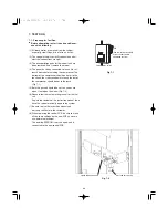
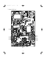
Page 35: ...35 7 3 Outdoor Unit PCB Setting CN51 CN50 D043 LED2 D042 LED1 S003 CN33 S002 S004 Fig 7 4...
Page 46: ...46...
Page 47: ...47...
Page 48: ...DC0811 0 Printed in Japan...


