


21
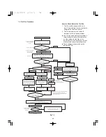
3. HOW TO INSTALL THE OUTDOOR UNIT
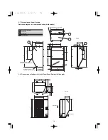
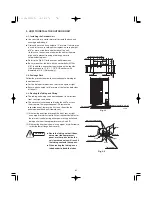
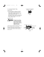
3-1. Installing the Outdoor Unit
●
Use concrete or a similar material to create the base, and
ensure good drainage.
●
Ordinarily, ensure a base height of 2" or more. If a drain pipe
is used, or for use in cold-weather regions, ensure a height
of 6" or more at the feet on both sides of the unit.
(In this case, leave clearance below the unit for the drain
pipe, and to prevent freezing of drainage water in
cold-weather regions.)
●
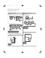
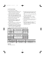
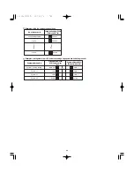
Refer to the Fig. 3-1 for the anchor bolt dimensions.
●
Be sure to anchor the feet with the anchor bolts (M10 or
3/8"). In addition, use anchoring washers on the top side.
(Use large square 1-1/4"
×
1-1/4" SUS washers with
diameters of 3/8".) (Field supply)
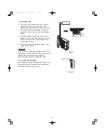
3-2. Drainage Work
Follow the procedure below to ensure adequate draining for
the outdoor unit.
●
For the drain port dimensions, refer to the figure at right.
●
Ensure a base height of 6" or more at the feet on both sides
of the unit.
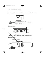
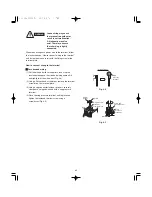
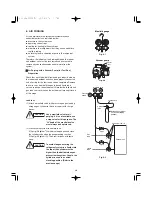
3-3. Routing the Tubing and Wiring
●
The tubing and wiring can be extended out in 4 directions:
front, rear, right, and down.
●
The service valves are housed inside the unit. To access
them, remove the inspection panel. (To remove the
inspection panel, remove the 3 screws, then slide the
panel downward and pull it toward you.)
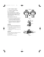
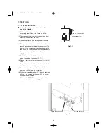
(1) If the routing direction is through the front, rear, or right,
use a nipper or similar tool to cut out the knockout holes for
the inter-unit control wiring outlet, power wiring outlet, and
tubing outlet from the appropriate covers A and B.
(2) If the routing direction is down, use a nipper or similar tool to
cut out the lower flange from cover A.
Fig. 3-1
37
11-21/32
5-29/32
8-5/8
33/64
3/4
25/32
19/32
25/64
14-61/64
15-15/16
13-13/64
33/64
33/64
6-47/64
25-63/64
4-3/8
Drain port (2 locations)
Drain port
Anchor bolt (M10 or 3/8")
33/64
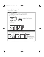
Fig. 3-2
Inspection panel
Cover A
Cover B
Power supply
Tubing outlet
Down
Front
Rear
Right
Inter-unit control wiring
CAUTION
●
Route the tubing so that it does
not contact the compressor,
panel, or other parts inside the
unit. Increased noise will result if
the tubing contacts these parts.
●
When routing the tubing, use a
tube bender to bend the tubes.
Unit: in.
Summary of Contents for U-36LE1U6
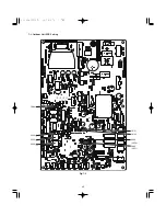
Page 35: ...35 7 3 Outdoor Unit PCB Setting CN51 CN50 D043 LED2 D042 LED1 S003 CN33 S002 S004 Fig 7 4...
Page 46: ...46...
Page 47: ...47...
Page 48: ...DC0811 0 Printed in Japan...


