23
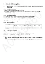
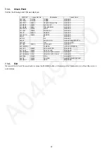
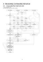
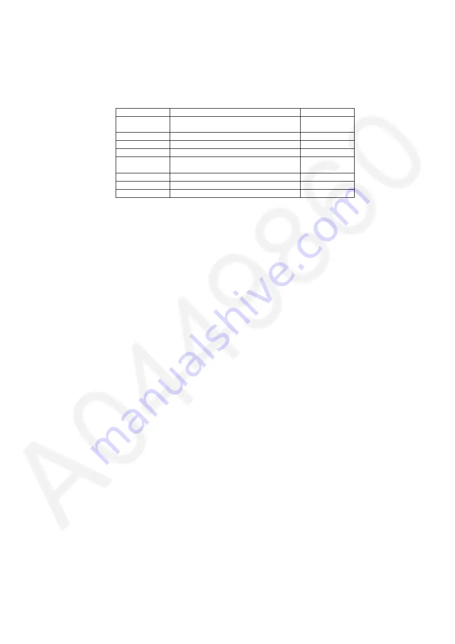
7.2.
Power LED Blinking timing chart
1. Subject
Information of LED Flashing timing chart.
2. Contents
When an abnormality has occurred the unit, the protection circuit operates and reset to the stand by mode. At this time, the
defective block can be identified by the number of blinks of the Power LED on the front panel of the unit.
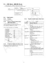
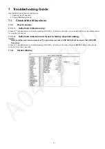
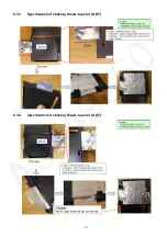
7.3.
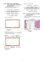
LCD Panel / FR test mode
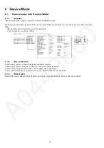
Purpose:
To find the possible failure point where in LCD Panel, FR board or A board when the abnormal picture is displayed.
Procedure:
Step 1. Go into LCD Panel test mode and confirm the symptom
While pressing [VOLUME ( - )] button of the main unit, press [OPTION] button of the remote control three times within 2
seconds.
The several test patterns generated by LCD Panel are displayed. Judge by the following method.
Still abnormal picture is displayed: The cause must be in LCD Panel. Exit test mode.
Normal picture is displayed: The cause must be in A board or FR board. Go into FR test mode
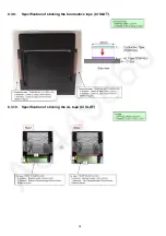
Step 2. Go into FR test mode and confirm the symptom
During in LCD Panel test mode, press [OK] button on the remote control.
The test pattern generated by FR board is displayed. Judge by the following method.
Abnormal picture is displayed: The cause must be in FR board.
Normal picture is displayed: The cause must be in A board.
Step 3. How to Exit:
Switch off the power with the [POWER] button on the main unit or the [POWER] button on the remote control in LCD Panel test
mode or FR test mode.
Blinking Times
Contents
Check point
1
BL SOS
LCD PANEL
P-Board
3 (fast blinking)
IROM SOS
A-Board
6
FPGA SOS
A-Board
7
SUB 3.3V
A-Board
9
SOUND SOS
A-Board
Speaker
10
GCX/FRC SOS
FR-Board
12
BE SOS
A-Board
13
EMERGENCY SOS
A-Board
Summary of Contents for TX-58AXR800
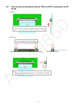
Page 13: ...13 5 4 How to connect and disconnect for FR12 and FR13 connectors on FR board ...
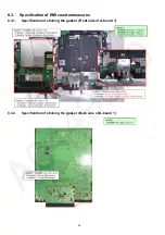
Page 39: ...39 8 3 11 Specification of sticking the AL tape Gasket CI SLOT ...
Page 40: ...40 8 3 12 Specification of sticking Gasket CI SLOT Back cover side ...
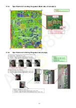
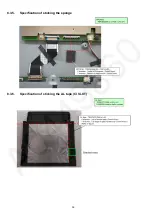
Page 49: ...49 8 3 29 Specification of sticking the gasket 8 3 30 Specification of sticking the gasket ...
Page 50: ...50 8 3 31 Specification of sticking the gasket 8 3 32 Specification of sticking the gasket ...
Page 51: ...51 8 3 33 Specification of sticking the gasket 8 3 34 Specification of sticking the gasket ...
Page 53: ...53 8 3 37 Specification of sticking the gasket ...
Page 59: ...59 11 Wiring Connection Diagram 11 1 Wiring Diagram ...
Page 61: ...61 ...
Page 62: ...62 ...
Page 63: ...63 ...


