

32
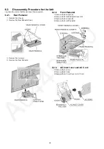
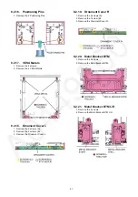
8.2.22. Rear Panel L/R
1. Remove the 2 screws.
2. Remove the Rear Panel L/R.
8.2.23. Rear Panel T
1. Remove the 2 screws.
2. Remove the Rear Panel T.
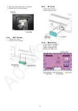
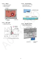
8.2.24. MD-Board
1. Disconnect the connector (M08).
2. Remove the 2 hooks.
3. Remove the MD-Board.
8.2.25. K-Board
1. Remove the 2 hooks.
2. Disconnect the connector (K10).
3. Remove the K-Board.
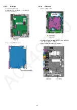
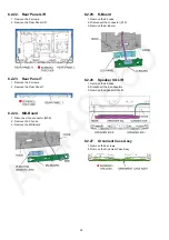
8.2.26. Speaker SQ L/R
1. Remove the 4 hooks.
2. Disconnect the 2 connectors.
3. Remove the Speaker SQ L/R.
8.2.27. Ornament Case Assy
1. Remove the 2 screws.
2. Remove the Ornament Case Assy.
Summary of Contents for TX-58AXR800
Page 13: ...13 5 4 How to connect and disconnect for FR12 and FR13 connectors on FR board ...
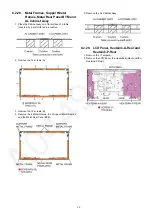
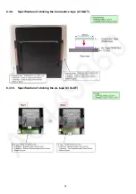
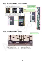
Page 39: ...39 8 3 11 Specification of sticking the AL tape Gasket CI SLOT ...
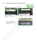
Page 40: ...40 8 3 12 Specification of sticking Gasket CI SLOT Back cover side ...
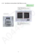
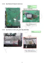
Page 49: ...49 8 3 29 Specification of sticking the gasket 8 3 30 Specification of sticking the gasket ...
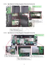
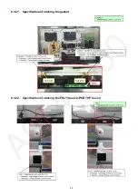
Page 50: ...50 8 3 31 Specification of sticking the gasket 8 3 32 Specification of sticking the gasket ...
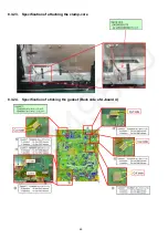
Page 51: ...51 8 3 33 Specification of sticking the gasket 8 3 34 Specification of sticking the gasket ...
Page 53: ...53 8 3 37 Specification of sticking the gasket ...
Page 59: ...59 11 Wiring Connection Diagram 11 1 Wiring Diagram ...
Page 61: ...61 ...
Page 62: ...62 ...
Page 63: ...63 ...


