
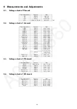

55
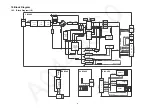
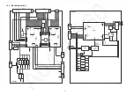
10 Block Diagram
10.1. Block Diagram (1/3)
Line
Filter
LF7106
F7101
1
4
2
3
Line
Filter
LF7107
3
2
4
1
CF7104
~
~
+
-
D7102
D7104
D7105
IC7301
14
VS
9
VW
Resonant
Controller
HOT
COLD
PC7301
Photo coupler
1
VH
4
FB
P2
T
O
A02 / FR20
17
POWER_ON
20
19
18
IC7401
Line
Filter
LF7105
3
2
4
1
T7201
1
3
IC7201
PFC
Control IC
7
OUT
8
VCC
Q7201
Q7202
4
3
T7301
PC7303
Photo coupler
PC7302
Photo coupler
SUB_ON
D7305
6
REF
10
VCC
6
D7304
12,7
14,9
Q7401
P-BOARD
GK-BOARD
GK4
SW2855
SW2854
SW2853
SW2852
SW2851
KEY1
SW2857
3
2
T
O P5
POWER_ON
K-BOARD
K10
7
3
4
5
6
1
SUB3.3V
STBY3.3V
RM2800
VCC
OUT
SN2800
AI
3
1
VCC
OUT
D2802
R
G
TO
A
1
0
REMOTE
AI
G_LED_ON
R_LED_ON
SUB3.3V
AI
STBY 3.3V
STBY 3.3V
R_LED_ON
G_LED_ON
REMOTE
RL7101
9-12
Q7315
3
PGS
T7202
1
3
Q7203
4
3
T7302
14,9
P4
T
O LD
24V
1-4
BL_SOS
9
BL_ON
10
P5
3
2
T
O GK4
KEY
22
BL_ON
BL_SOS
SUB_ON
5VS
15
16V
12,7
Q7402
Q7404
24V
Q7403
Q7405
16V
IC7503
DC/DC
3
2
5VS
6
10
13
13
10
IC7402
Sync rectifier
smart driver
3
DVS1
4
DVS2
8
VCC
Q7418
MD-BOARD
M08
2
3
TO A10
IC2870
Amplifier
7
8
OUT
V+
3
IN
SN2870
3
1
V
out
SENSOR_OUT
3.3V
Vi
n
P1
Main Input
1
2
CF7103
PC7304
Photo coupler
1-4
16V
Q7406
HUM_VCC_ON
21
HUM_VCC_ON
Summary of Contents for TX-58AXR800
Page 13: ...13 5 4 How to connect and disconnect for FR12 and FR13 connectors on FR board ...
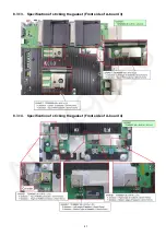
Page 39: ...39 8 3 11 Specification of sticking the AL tape Gasket CI SLOT ...
Page 40: ...40 8 3 12 Specification of sticking Gasket CI SLOT Back cover side ...
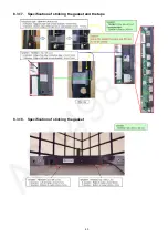
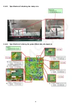
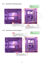
Page 49: ...49 8 3 29 Specification of sticking the gasket 8 3 30 Specification of sticking the gasket ...
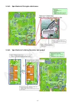
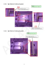
Page 50: ...50 8 3 31 Specification of sticking the gasket 8 3 32 Specification of sticking the gasket ...
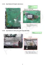
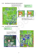
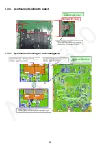
Page 51: ...51 8 3 33 Specification of sticking the gasket 8 3 34 Specification of sticking the gasket ...
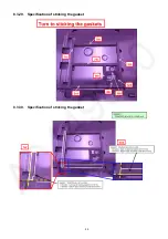
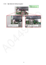
Page 53: ...53 8 3 37 Specification of sticking the gasket ...
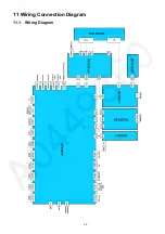
Page 59: ...59 11 Wiring Connection Diagram 11 1 Wiring Diagram ...
Page 61: ...61 ...
Page 62: ...62 ...
Page 63: ...63 ...


