
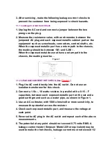


milliamp. In case a measurement is outside of the limits specified,
there is a possibility of a shock hazard, and the equipment should
be repaired and rechecked before it is returned to the customer.
2. Prevention of Electro Static Discharge (ESD) to
Electrostatically Sensitive (ES) Devices
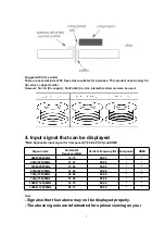
Some semiconductor (solid state) devices can be damaged easily by static electricity. Such
components commonly are called Electrostatically Sensitive (ES) Devices. Examples of typical
ES devices are integrated circuits and some field-effect transistors and semiconductor "chip"
components. The following techniques should be used to help reduce the incidence of
component damage caused by electro static discharge (ESD).
1. Immediately before handling any semiconductor component or
semiconductor-equipped assembly, drain off any ESD on your
body by touching a known earth ground. Alternatively, obtain and
wear a commercially available discharging ESD wrist strap, which
should be removed for potential shock reasons prior to applying
power to the unit under test.
2. After removing an electrical assembly equipped with ES devices,
place the assembly on a conductive surface such as aluminum
foil, to prevent electrostatic charge buildup or exposure of the
assembly.
3. Use only a grounded-tip soldering iron to solder or unsolder ES
devices.
4. Use only an anti-static solder removal device. Some solder
removal devices not classified as "anti-static (ESD protected)"
can generate electrical charge sufficient to damage ES devices.
5. Do not use freon-propelled chemicals. These can generate
electrical charges sufficient to damage ES devices.
6. Do not remove a replacement ES device from its protective
package until immediately before you are ready to install it. (Most
replacement ES devices are packaged with leads electrically
shorted together by conductive foam, alminum foil or comparable
conductive material).
7. Immediately before removing the protective material from the
leads of a replacement ES device, touch the protective material to
the chassis or circuit assembly into which the device will be
5
Summary of Contents for TX-32LX60M
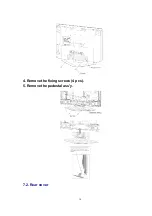
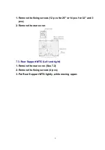
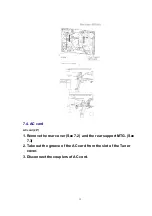
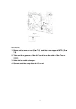
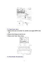
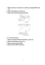
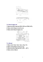
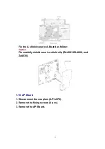
Page 10: ...4 Remove the fixing screws 4 pcs 5 Remove the pedestal ass y 7 2 Rear cover 10 ...
Page 24: ...8 Location of Lead Wiring Location of Lead Wiring 26 Location of Lead Wiring 32 24 ...
Page 25: ...9 EMI Processing EMI Processing 26 EMI Processing 32 25 ...
Page 27: ...10 3 Option Description 27 ...
Page 28: ...28 ...
Page 33: ...32 15 Packing Exploded View 26 33 ...
Page 34: ...32 34 ...
Page 36: ...17 2 Electrical Replacement Parts List 18 SCHEMATIC DIAGRAM FOR PRINTING WITH A4 36 ...