

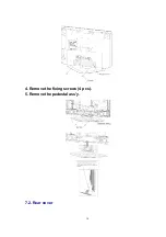
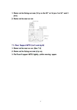
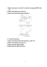


1. Remove the rear cover (See 7.2) and the rear support MTG. (See
7.3)
2. Remove the fixing screws (2 pcs).
3. Remove the Power Button Bracket Ass’y.
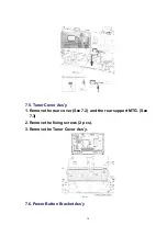
7.7. Control Panel Ass’y
1. Remove the Power Button Bracket Ass’y. (See 7.5)
2. Remove the fixing screws (2 pcs).
3. Disconnect the coupler (AP6).
4. Remove the Control Panel Ass’y.
15
Summary of Contents for TX-32LX60M
Page 10: ...4 Remove the fixing screws 4 pcs 5 Remove the pedestal ass y 7 2 Rear cover 10 ...
Page 24: ...8 Location of Lead Wiring Location of Lead Wiring 26 Location of Lead Wiring 32 24 ...
Page 25: ...9 EMI Processing EMI Processing 26 EMI Processing 32 25 ...
Page 27: ...10 3 Option Description 27 ...
Page 28: ...28 ...
Page 33: ...32 15 Packing Exploded View 26 33 ...
Page 34: ...32 34 ...
Page 36: ...17 2 Electrical Replacement Parts List 18 SCHEMATIC DIAGRAM FOR PRINTING WITH A4 36 ...