


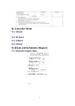


13.2. Main Block Diagram
13.3. P.B.C. Block Diagram
13.4. Signal Schematic Diagram
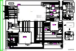
13.5. A-Board (1 of 5) Schematic Diagram
13.6. A-Board (2 of 5) Schematic Diagram
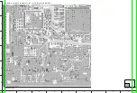
13.7. A-Board (3 of 5) Schematic Diagram
13.8. A-Board (4 of 5) Schematic Diagram
13.9. A-Board (5 of 5) Schematic Diagram
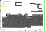
13.10. AP-Board (1 of 2) Schematic Diagram
13.11. AP-Board (2 of 2) Schematic Diagram
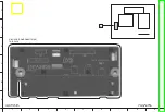
13.12. G and V-Board Schematic Diagram
14. Parts Location & Mechanical Replacement Parts
List
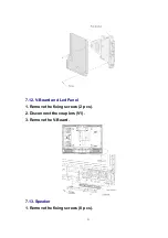
14.1. Parts Location
26"
32
Summary of Contents for TX-32LX60M
Page 10: ...4 Remove the fixing screws 4 pcs 5 Remove the pedestal ass y 7 2 Rear cover 10 ...
Page 24: ...8 Location of Lead Wiring Location of Lead Wiring 26 Location of Lead Wiring 32 24 ...
Page 25: ...9 EMI Processing EMI Processing 26 EMI Processing 32 25 ...
Page 27: ...10 3 Option Description 27 ...
Page 28: ...28 ...
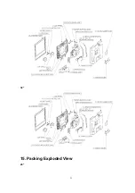
Page 33: ...32 15 Packing Exploded View 26 33 ...
Page 34: ...32 34 ...
Page 36: ...17 2 Electrical Replacement Parts List 18 SCHEMATIC DIAGRAM FOR PRINTING WITH A4 36 ...