background image

51

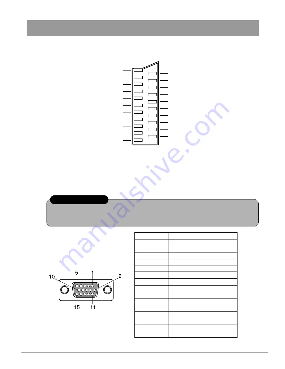
21- pol SCART AV Connector

15 - pin Mini D-sub Connector

Signals names of pins are
shown in the table on the
right.

* VESA-DDC standard.

Pin No.

Signal

1

Red signal

2

Green signal

3

Blue signal

4

Ground

5

Ground*

6

Ground for red signal

7

Ground for green signal

8

Ground for blue signal

9

Not used

10

Ground

11

Ground

12

SDA*

13

Horizontal sync signal

14

Vertical sync signal

15

SCL*

Audio signal output, right ch.   1

  2  Audio signal input, right ch.

Audio signal output, left ch.   3

  4  Audio signal “ground”

  6  Audio signal input, left ch.

B-signal ground   5

  8  Switching voltage

B-signal input   7

G-signal ground   9

10  –––––

G-signal input  11

12  –––––

“Masse” des R - Signals  13

14  Ground

R-signal input  15

16  Switching voltage for RGB

FBAS ground  17

18  RGB status ground

FBAS output (video)  19

20  FBAS input (video)

Ground for plug  21

AV is RGB-compatible.

Do not modify the cable and do not try to construct your own cable.
Using a wrong cable can damage the computer.

Precaution

APPENDIX

Summary of Contents for TX-15TA1C

Page 1: ...TX 15TA1C TQBE0428 Please read these instructions before operating your set and retain them for future reference Multi Media Terminal LCD Monitor with Tuner Operating Instructions ...

Page 2: ...ation is essential to prevent failure of electrical components we recommend that a gap of at least 5 cm is left around the unit even when it is placed inside a cabinet or between shelves WASTE DISPOSAL The used packaging and batteries should be disposed of in special containers intended for this purpose CE CONFORMITY This device complies with the requirements of EEC directive 89 336 EEC as amended...

Page 3: ...he equipment is not used for long time disconnect the equipment from socket outlet to avoid being damaged by transient overvoltage Never pour any liquid into openings this could cause fire or electric shock Never open the equipment For safety reason the equipment should only be opened by qualified service personnel If one of the following situations arises get the equipment checked by a service pe...

Page 4: ... System menu 41 On screen functions 43 Power management functions 43 Preset mode 44 Security port 45 Care 45 Trouble shooting 46 Specifications 50 Pin assignment 51 21 pin SCART AV port 51 15 pin Mini D Sub connector 51 User information Accessories 5 Preparing the remote control unit 6 Installing the stand 7 Connecting the monitor and Tuner 8 LC display operation 29 VGA is a registered trademark o...

Page 5: ... for Windows 95 98 It is not compatible with Windows NT and Mac OS For details please refer to file Readme_eng txt on the disk This read me file contains important information Please read the file and follow the instructions This unit conforms to VESA DDC To use the plug play function your computer and graphics card must also conform to this standard For details please refer to the instruction man...

Page 6: ...ing batteries label Do not drop the remote control unit subject it to hard shock or step on it this might cause breakage of parts and malfunction Make sure there are no obstacles between the remote control unit and the remote control reception sensor on the monitor Do not use the remote control unit at the same time as a remote control unit for other devices Replace the battery if the remote contr...

Page 7: ...on a stable surface Place the Tuner stand so that the arrow is positioned in front see illustration below 1 2 Securely slide the Tuner into the stand 3 Placing the monitor on the Tuner Upright positioning of the Tuner Please use the supplied stand for the Tuner Precaution Precaution Align the mark on the bottom of the Tuner with the mark on the Tuner stand ...

Page 8: ...ct the cable first disconnect the power adapter After connecting the cables please attach the cable cover to the rear of the monitor in order to protect the cables Insert the three tabs on the upper side of the cable cover into the holes of the connection section on the rear of the monitor 1 Slide the two sides of the lower part of the cable cover into position until they audibly click into place ...

Page 9: ... properly connected to this unit using a suitable cable OR SCART 2 2 1 3 PC AV Connect the power cord to the power adapter Then connect the DC plug to the Tuner and the power plug to the power outlet Turn the unit ON by pressing the power switch 1 2 3 ...

Page 10: ...aved in memory and organized see page 25 Press button F if you want to stop Press button N if you want to cancel theATP sequence Select your language 4 Press the TV AV button Select your country Press the TV AV button 5 Channel selection Volume adjustment QUICK START continued ...

Page 11: ...e unit on off for TV AV and PC operation Stand by Channel number up and down menu line selection Teletext page selection Recalls the levels selected with the STR button on the unit front panel Cancels the menu indication on the screen Channel direct selection Press and select the channel on the numbered buttons If you want to select a channel in the HYPERBAND cable TV with the direct channel selec...

Page 12: ...nd other function adjustments STR TV AV mode selection see page 22 Thisbuttonisusedtosaveandconfirm the screen menu indications Power indicator Remote control signal sencor Main power supply Standby for remote control mode Normal operation DPMS standby TV AV Black Off Yellow Black Off PC Black Off Yellow Green LED color Yellow _ Power switch On Off PC switch TUNER switch MAIN CONTROLS continued Pr...

Page 13: ...he selected parameter Button TV AV is normally used to confirm the selection Selected line Instructions Press button F to enter the menu Main Menu Contrast Brightness Colour Sharpness off timer Sound Menu Setup Menu Sound Menu Volume Bass Treble Balance MPX TV only Mode AI Setup Text Language Aspect Colour System AV only Tuning Menu OSD Language Tuning Menu ATP Manual tuning Fine tuning Swap Volum...

Page 14: ...lect the required parameter Increase or decrease the level Contrast Off timer Sound menu Setup menu Brightness Colour Sharpness Tint Switches off your teltvision at the time you set from 0 to 90 minutes with 15 mnute intervals The line Tint will appear as a menu line only when a NTSC signal is connected to the unit via the AV input thus allowing the tints to be adjusted The Setup menu provides acc...

Page 15: ...This section shows how to adjust the sound as you wish The sound quality may be changed by selecting the Music or Speech modes Select the required parameter Adjust the level and confirm the selection Balance MPX is set in position Stereo in case of stereo transmission thus ensuring the best sound reproduction However if transmission deteriorates you are recommended to switch over to Mono Mono M1 a...

Page 16: ...d volume tuning See page 17 Select the required parameter Adjust the parameter Allows selection of the language to be used in all the menus Tuning Menu SETUP MENU Switches between western and eastern character set in Teletext Text Language The Aspect function will allow you to view wide screen programs with the correct side dimensions 16 9 Aspect OSD Language Selects the colour decoding system for...

Page 17: ...ovides access to the manual and automatic tuning menu TV MEMORY MENU Allows manual tuning of the selected channels See page 19 Enter the required parameter Swaps the programmes as you prefer See page 21 The broadcasting stations may be finely tuned to with the Fine tuning function Allows the volume to be set for different broadcasting stations with different sound levels Locks the programme positi...

Page 18: ... stations TUNING MENU AUTOMATIC TUNING PROCESS ATP Select your country Press to start the automatic tuning process ATP The television will find tune into and sort the local broadcasting station As soon as this operation is completed programme position 1 will be displayed on the screen Select ATP Select Access Press to start Press button F to interrupt and N to finish the ATP sequence ...

Page 19: ...al tuning Select the program position you need TUNING MANUAL TUNING The programme positions may be tuned manually either with the on screen menu or with the buttons on the front panel Leave the menu by pressing button N When the required programme is found save it by pressing either button TV AV or STR on the front panel of the Tuner ...

Page 20: ...band cable TV press the direct channel selection button and programme position button C and one after the other and set the number with the numbered buttons CH will first appear in the left top corner of the screen and then H For saving see above Note TUNER front panel By pressing button or enter Manual tuning By pressing buttons or change the programme position to start the search or change the T...

Page 21: ...ws you to swap between two programme positions Leave the menu by pressing button N Press button F Select Setup menu Enter Setup menu Save and leave the menu by pressing button N Enter OSD Language Select the language OSD LANGUAGE When first setting up your television select the OSD language to match your country selection If you want to use another language you may select the language from the lan...

Page 22: ...gramme is changed You may switch back to the television by pressing button TV AV or by disconnecting the AV device two AV devices may not be connected to the television simultaneously as their signals would overlap In the AV mode the Setup menu is extended to include Colour System If a NTSC signal is connected via the AV inputs the television will automatically detect the signal and switch over to...

Page 23: ...eletext pages Any page becomes instantly accessible by pressing the appropriate button How is it operated TOP uses four differently colored buttons red green yellow and blue to select required information To select the subject e g Sports use the blue button Within sports different groups may be selected such as tennis football baseball etc by pressing the yellow button When the last group of the s...

Page 24: ...election Youcanselectpagesintwodifferentways a Press one of the keys to change the page number by 1 or b enter the desired page number using the keys 0 9 on the remote control Normalization When Teletext information exceeds more than one page it may take some time for the automatic changing of the sub pages to reach the sub page you require Press the TIME TEXT button will be displayed at the top l...

Page 25: ...s which are not listed in the table in the increasing order of programme positions then TV stations where the TV receiver has not identified the name in the increasing order of programme positions For other European countries the programme positions are sorted and stored in the order of tuning No 1 2 3 4 5 6 7 8 9 10 11 12 13 14 15 16 17 18 19 20 21 22 23 24 25 26 27 GERMANY ARD ZDF N3 RTL SAT1 VO...

Page 26: ... headphones are connected the speakers will be automatically disconnected Do not connect AV inputs on the front and rear panels simultaneously as the sound and video signals will overlap Audio video AV inputs are designed to connect a VTR and satellite receiver or other compatible audio video system VCR SCART cable SATELLITE RECEIVER CAMERA GAME CONSOLE EXTERNAL AUDIO VIDEO CONNECTION ...

Page 27: ...T Headphones jack Headphones with 3 5 mm male jack Amplifier to speaker system Connect the headphones earphones as shown below Notes The volume of the audio output jack AUDIO OUT can be controlled using the buttons on the Tuner or remote control unit If the volume has been set to zero on this unit no sound will be heard even when the speaker or headphone volume is raised EXTERNAL AUDIO VIDEO CONNE...

Page 28: ...28 ...

Page 29: ...29 LC DISPLAY OPERATION ...

Page 30: ...nect the signal cable to the video output connector of the computer Audio Connect the audio cable to the PC audio input PC IN AUDIO Connect the audio cable to the audio output connector of the computer Rear panel of com puter Connector section on rear panel Supplied signal cable Supplied audio cable Rear panel of the monitor Video output connector Connector PC IN VIDEO Connector PC IN AUDIO Connec...

Page 31: ... PC mode The mode changes every time the button is pressed buttons To select items for settings F button Displays and removes the menu or turns it back by one step Remote Control Unit buttons These buttons are usually used for volume control In menu operations they can be used to switch functions or make settings ON SCREEN button Turns on and off the on screen display during menu operations STAND ...

Page 32: ...o the previous menu screen VOL buttons Volume These buttons are usually used for volume control In menu operations they are used for selecting and changing or setting operations Speakers Monitor front side Operation indicator Power on Lights green Economy mode Lights yellow Standby mode Lights orange Reception sensor for remote control Power switch To turn on and off the power supply Pressing this...

Page 33: ...ton again turns the sound back on The menu screen is displayed by pressing the button F button MENU Press this button to reset values to the standard settings Return to default Normalize or or Switching between TV AV mode and PC mode Displaying the menu screen Displaying input status frequency The status of the input frequencies fH and fV is displayed by pressing the button ON SCREEN Remote contro...

Page 34: ...ed to explain the procedure of moving through sub menus to select and set parameters Various functions such as backlight contrast and brightness can be controlled individually Various options such as sharp ness can be selected individually Pressing the button F opens the main menu or returns to the previous menu Press the button ON SCREEN and close the menu Press the buttons or to select a sub men...

Page 35: ...5 display Press the buttons or to select your setting See pages 36 to 37 See page 40 Press the buttons or to select a sub menu Press the buttons or to select an item See pages 38 to 40 See pages 41 to 42 ...

Page 36: ...tting backlight contrast and brightness Adjust as desired while looking at the picture on the screen BACKLIGHT To adjust the brightness of the screen background CONTRAST To set the screen contrast BRIGHTNESS black level To adjust the brightness of the screen SHARPNESS To select the sharpness of the screen GAMMA To select or control the relative brightness according to ambient light conditions COLO...

Page 37: ... can be set as desired Press the buttons or to display the USER mode Press the buttons or to set the desired compensation Selecting and setting colour temperature COLOUR TEMP PICTURE MENU continued To finish setting Press the button ON SCREEN Press the buttons or to switch to the respective mode Renders a somewhat bluish white Default setting Screen colour temperature about 9400K Renders a somewha...

Page 38: ... computer Select a pattern that displays over the full screen For details refer to the instruction manual of the computer you use This does not work in VGA350 mode This does not work on screens with just the DOS input prompt Perform the adjustment manually Depending on the clock rate it may not be possible to make this adjustment Depending on the input signal input clock rate or the video card aut...

Page 39: ...rs in characters 2 Move to DOT CLOCK and press or to adjust the vertical lines of the screen 3 Move to PHASE and adjust by press or Precautions There can be more than one acceptable dot Depending on the dot selected there can be a missing dot to the left or right In such a case move to a different dot and readjust horizontal position and clock phase Depending on the video card and refresh rate set...

Page 40: ...ncement for software SOUND MENU RECALL Resetting to the default standard setting Press the buttons or to select YES or NO YES The setting is reset to the default setting NO The present setting is retained If about 20 seconds elapse without operation the present setting is retained and the menu disappears Standard setting RECALL To finish setting Press the buttons ON SCREEN To finish setting Press ...

Page 41: ...Setting artificial intelligence for the LC display Press the buttons or to select OFF 4 3 or 16 9 OFF Artificial intelligence for the LC display suspended 4 3 For video reproduction with aspect ratio 4 3 16 9 For video reproduction with aspect ratio 16 9 Notes For correct results of this adjustment a white area about as large as the mouse cursor is required If the adjustment is performed while no ...

Page 42: ...nc frequencies of the input signal are displayed RECALL ALL Standard settings All settings are reset to the standard settings This does not apply to the sound menu and the artificial intelligence for the LC display Press the buttons or to select YES or NO YES The standard settings are recalled NO The present settings are retained If about 20 seconds elapse without operation the present settings ar...

Page 43: ...itor If no input signal is present Self test indicator If the input frequency is located outside the permitted range Input error indicator If this unit is used with a computer corresponding to VESA DPMS standard current consumption can be reduced For details please refer to the following table This mode can not be set on this unit The function is permanently active The DPMS mode power management m...

Page 44: ...e the refresh rate vertical sync frequency of the computer or change the resolution and set the clock to the default setting Caution Horizontal frequency Horizontal sync polarity Horizontal size Horizontal position Total number of vertical lines Vertical sync polarity Vertical size Vortical position DOT CLOCK PHASE Sharpness Video signal level 640 480 640 400 640 480 640 480 640 480 800 600 800 60...

Page 45: ...ith a wet cloth Please use gauze or a soft cloth to softly wipe the display In the case of obstinate stains slightly moisten the gauze or cloth with an office cleaning agent for LC displays and softly wipe the display to remove them Do not use acetone or other ketones xylol toluol or other solvents or water Wipe the cabinet with a soft cloth To remove obstinate soiling moisten a soft cloth with a ...

Page 46: ...nnect correctly to headphones jack 27 Picture displayed but no sound Is muting MUTE activated Is volume VOL set to minimum Is the audio cable connected correctly 22 33 11 12 31 33 26 27 30 Picture too dark Adjust backlight only PC mode contrast and brightness 14 36 No picture displayed Power supply turned OFF Monitor and TUNER connected Signal cable correctly connected If in PC mode cancel power m...

Page 47: ... TV power is turned on picture and sound controls are set to minimum the TV is in standby mode 11 12 9 9 11 12 11 No color but normal sound Colour reproduction set to minimum values Inferior or distorted picture low or no sound Station tuning Please retune the unit or use fine tuning 17 20 Normal picture but low or distorted sound Sudden deterioration of reception conditions e g atmospheric condit...

Page 48: ...re distorted Vertical lines may appear distorted due to reception channel changes However this is not a malfunction No picture Power turned OFF Does the equipment connected to the Tuner function properly Connect the signal cable correctly 12 9 26 27 Symptom Check See pages Vertical or horizontal stripe patterns appear Run VIDEO LEVELAUTO automatic video level setting after automatic size adjustmen...

Page 49: ...er the vertical frequency of the video signal and move the clock frequency into the predetermined range 80 MHz For details refer to the instruction manual of the computer 39 Picture too dark Check the video level from the computer and set the monitor video level accordingly Adjust backlight contrast and brightness 41 36 Harsh character contours Set sharpness picture quality to mode 1 37 Press only...

Page 50: ... antiglare hard coating viewing angle 70 R L 55 upwards 70 downwards frequency response 23 ms brightness setting 300 cd m2 contrast ratio 500 1 Monitor 385 mm W 343 mm H 170 mm T Monitor 385 mm W 343 mm H 170 mm T TUNER 280 mm W 45 mm H 180 mm T Monitor 4 4 kg TUNER 1 5 kg PAL B PAL G PAL H PAL 60 VHF E2 E12 UHFE21 E69 CATV S01 S05 CATV S1 S10 M1 M10 CATV S11 S20 U1 U10 CATV S21 S41 Hyperband AV N...

Page 51: ...5 SCL Audio signal output right ch 1 2 Audio signal input right ch Audio signal output left ch 3 4 Audio signal ground 6 Audio signal input left ch B signal ground 5 8 Switching voltage B signal input 7 G signal ground 9 10 G signal input 11 12 Masse des R Signals 13 14 Ground R signal input 15 16 Switching voltage for RGB FBAS ground 17 18 RGB status ground FBAS output video 19 20 FBAS input vide...

Page 52: ...n If service is required contact your local Panasonic dealer and quote the type and serial numbers of the unit both can be found on the rear panel Storing the last setting The following settings are stored automatically These will be reused automatically when you turn the TV back on Program position Tint Audio reception Volume compensation AV Contrast stereo mono M1 M2 Volume Sharpness Surround so...

Reviews: