37
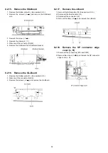
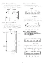
8.2.26. Remove the C3-Board
1. Unlock the cable clampers to free the cable.
2. Remove the DD-Heat-sink fastening screws (
×
10 ).
3. Remove the DD-Heat-sink (
×
5).
4. Disconnect the flexible cables (CB11, CB12, CB13, CB14
and CB15).
5. Disconnect the flexible cable (C36).
6. Disconnect the connectors (C33 and C35).
7. Remove the screws (
×
4
) and remove the C3-Board.
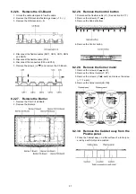
8.2.27. Remove the Barrier
1. Remove the Print Circuit Board.
2. Remove the Barriers.
8.2.28. Remove the Control button
1. Disconnect the flexible cable (J1). (See section 8.2.17.)
2. Remove the screws (
×
11 ).
3. Remove the Cabinet bottom.
4. Remove the Control button.
8.2.29. Remove the Corner metal
1. Remove the screws (
×
3
each).
2. Remove the Corner metal (LT, RT).
3. Remove the screws (
×
3
each) and remove the screw
(
×
1
each).
4. Remove the Corner metal (LB, RB).
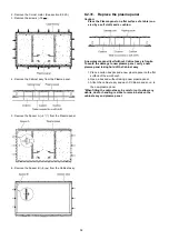
8.2.30. Remove the Cabinet assy from the
Plasma panel.
1. Place the Cabinet assy on a flat surface of a table (cov-
ered by a soft cloth) and a cushion.
Summary of Contents for TH-P54Z1D
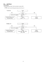
Page 24: ...24 6 4 No Picture ...
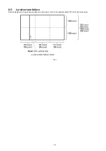
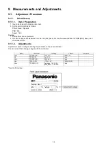
Page 41: ...41 9 1 4 Adjustment Volume Location 9 1 5 Test Point Location ...
Page 42: ...42 ...
Page 54: ...54 11 3 Wiring Display unit 1 11 4 Wiring Display unit 2 ...
Page 55: ...55 11 5 Wiring Display unit 3 11 6 Wiring Display unit 4 ...
Page 56: ...56 11 7 Wiring Display unit 5 11 8 Wiring Display unit 6 ...
Page 57: ...57 12 Schematic Diagram 12 1 Schematic Diagram Note ...
Page 146: ...146 ...
Page 148: ...148 14 1 2 Exploded View 2 Display unit ...
Page 149: ...149 14 1 3 Exploded View 3 Display unit ...
Page 150: ...150 14 1 4 Packing 1 ...
Page 151: ...151 14 1 5 Packing 2 ...
Page 152: ...152 14 1 6 Packing 3 ...
Page 153: ...153 14 1 7 Packing 4 Pedestal stand ...
Page 154: ...154 14 1 8 Packing 5 ...
Page 155: ...155 14 1 9 Packing 6 ...
Page 156: ...156 14 1 10 Packing 7 ...
Page 162: ...162 14 2 Electrical Replacement Parts List 14 2 1 Replacement Parts List Notes ...

