29
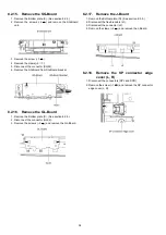
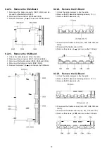
8.1.10. Remove the A-Board
1. Remove the Rear panel. (See section 8.1.2.)
2. Remove the DH-Board and DH-Board shield metal. (See
section 8.1.9.)
3. Unlock the cable clampers to free the cable.
4. Disconnect the flexible cables (A5 and A11).
5. Disconnect the connectors (A9, A12, A71, A72 and A81).
6. Disconnect the bridge connectors (A10-P9, A51-G51 and
A52-G52).
7. Remove the screws (
×
4
) and remove the A-Board.
Summary of Contents for TH-P54Z1D
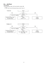
Page 24: ...24 6 4 No Picture ...
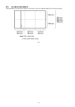
Page 41: ...41 9 1 4 Adjustment Volume Location 9 1 5 Test Point Location ...
Page 42: ...42 ...
Page 54: ...54 11 3 Wiring Display unit 1 11 4 Wiring Display unit 2 ...
Page 55: ...55 11 5 Wiring Display unit 3 11 6 Wiring Display unit 4 ...
Page 56: ...56 11 7 Wiring Display unit 5 11 8 Wiring Display unit 6 ...
Page 57: ...57 12 Schematic Diagram 12 1 Schematic Diagram Note ...
Page 146: ...146 ...
Page 148: ...148 14 1 2 Exploded View 2 Display unit ...
Page 149: ...149 14 1 3 Exploded View 3 Display unit ...
Page 150: ...150 14 1 4 Packing 1 ...
Page 151: ...151 14 1 5 Packing 2 ...
Page 152: ...152 14 1 6 Packing 3 ...
Page 153: ...153 14 1 7 Packing 4 Pedestal stand ...
Page 154: ...154 14 1 8 Packing 5 ...
Page 155: ...155 14 1 9 Packing 6 ...
Page 156: ...156 14 1 10 Packing 7 ...
Page 162: ...162 14 2 Electrical Replacement Parts List 14 2 1 Replacement Parts List Notes ...

