


30
TH-50VX100U / TH-50VX100E
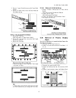
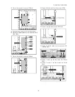
27. Remove 11 screws.
28. Pull the bottom of the Plasma Display Panel forward
(arrow1).
29. Slide the Plasma Display Panel and then remove the
Plasma Display Panel (arrow2).
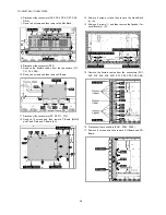
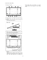
30. Remove the Rear Cover Hook Right and Rear Cover
Hook Left from the Plasma Display Panel.
31. Remove 8 Rear Cover Spacers and 8 Rear Cover Spacer
Rings from the Plasma Display Panel.
Caution:
• Please confirm the installation place of Rear Cover Hook
Right, Rear Cover Hook Left, Rear Cover Spacers and
Rear Cover Spacer Rings when you exchange the
Plasma Display Panel, and install them in an original
installation place after exchanging the Plasma Display
Panel.
Summary of Contents for TH-50VX100U
Page 7: ...7 TH 50VX100U TH 50VX100E 3 2 Applicable signals...
Page 8: ...8 TH 50VX100U TH 50VX100E...
Page 10: ...10 TH 50VX100U TH 50VX100E 5 Operating Instructions...
Page 15: ...15 TH 50VX100U TH 50VX100E 6 2 IIC mode structure following items value is sample data...
Page 33: ...33 TH 50VX100U TH 50VX100E 9 1 4 Adjustment Volume Location 9 1 5 Test Point Location...
Page 35: ...35 TH 50VX100U TH 50VX100E...
Page 37: ...37 TH 50VX100U TH 50VX100E...
Page 38: ...38 TH 50VX100U TH 50VX100E...
Page 47: ...47 TH 50VX100U TH 50VX100E 11 Wiring Connection Diagram 11 1 Wiring 1...
Page 48: ...48 TH 50VX100U TH 50VX100E 11 2 Wiring 2...
Page 49: ...49 TH 50VX100U TH 50VX100E 11 3 Wiring 3...
Page 50: ...50 TH 50VX100U TH 50VX100E...
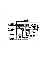
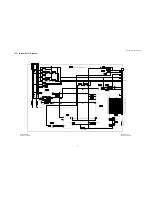
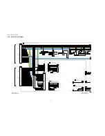
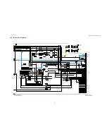
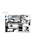
Page 51: ...TH 50VX100U TH 50VX100E 51 12 Schematic Diagram 12 1 Schematic Diagram Notes...
Page 169: ...Model No TH 50VX100U E Exploded View...
Page 170: ...Model No TH 50VX100U E Cabinet part location...
Page 171: ...Model No TH 50VX100U E Fan part location...
Page 172: ...Model No TH 50VX100U E Flat cable...
Page 173: ...Model No TH 50VX100U E Accessories...
Page 174: ...Model No TH 50VX100U E Packing 1...
Page 175: ...Model No TH 50VX100U E Packing 2...