

3
TH-50VX100U / TH-50VX100E
1 Safety Precautions
1.1.
General Guidelines
1. When conducting repairs and servicing, do not attempt to modify the equipment, its parts or its materials.
2. When wiring units (with cables, flexible cables or lead wires) are supplied as repair parts and only one wire or some of the
wires have been broken or disconnected, do not attempt to repair or re-wire the units. Replace the entire wiring unit instead.
3. When conducting repairs and servicing, do not twist the Faston connectors but plug them straight in or unplug them straight
out.
4. When servicing, observe the original lead dress.If a short circuit is found, replace all parts which have been overheated or
damaged by the short circuit.
5. After servicing, see to it that all the protective devices such as insulation barriers, insulation papers shields are properly
installed.
6. After servicing, make the following leakage current checks to prevent the customer from being exposed to shock hazards.
1.2.
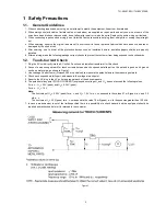
Touch-Current Check
1. Plug the AC cord directly into the AC outlet. Do not use an isolation transformer for this check.
2. Connect a measuring network for touch currents between each exposed metallic part on the set and a good earth ground
such as a water pipe, as shown in Figure 1.
3. Use Leakage Current Tester (Simpson 228 or equivalent) to measure the potential across the measuring network.
4. Check each exposed metallic part, and measure the voltage at each point.
5. Reserve the AC plug in the AC outlet and repeat each of the above measure.
6. The potential at any point (TOUGH CURRENT) expressed as voltage U
1
and U
2
, does not exceed the following values:
For a. c.: U
1
= 35 V (peak) and U
2
= 0.35 V (peak);
For d. c.: U
1
= 1.0 V,
Note:
The limit value of U
2
= 0.35 V (peak) for a. c. and U
1
= 1.0 V for d. c. correspond to the values 0.7 mA (peak) a. c. and 2.0
mA d. c.
The limit value U
1
= 35 V (peak) for a. c. correspond to the value 70 mA (peak) a. c. for frequencies greater than 100 kHz.
7. In case a measurement is out of the limits specified, there is a possibility of a shock hazard, and the equipment should be
repaired and rechecked before it is returned to the customer.
Figure 1
Summary of Contents for TH-50VX100U
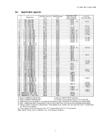
Page 7: ...7 TH 50VX100U TH 50VX100E 3 2 Applicable signals...
Page 8: ...8 TH 50VX100U TH 50VX100E...
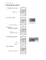
Page 10: ...10 TH 50VX100U TH 50VX100E 5 Operating Instructions...
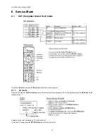
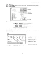
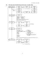
Page 15: ...15 TH 50VX100U TH 50VX100E 6 2 IIC mode structure following items value is sample data...
Page 33: ...33 TH 50VX100U TH 50VX100E 9 1 4 Adjustment Volume Location 9 1 5 Test Point Location...
Page 35: ...35 TH 50VX100U TH 50VX100E...
Page 37: ...37 TH 50VX100U TH 50VX100E...
Page 38: ...38 TH 50VX100U TH 50VX100E...
Page 47: ...47 TH 50VX100U TH 50VX100E 11 Wiring Connection Diagram 11 1 Wiring 1...
Page 48: ...48 TH 50VX100U TH 50VX100E 11 2 Wiring 2...
Page 49: ...49 TH 50VX100U TH 50VX100E 11 3 Wiring 3...
Page 50: ...50 TH 50VX100U TH 50VX100E...
Page 51: ...TH 50VX100U TH 50VX100E 51 12 Schematic Diagram 12 1 Schematic Diagram Notes...
Page 169: ...Model No TH 50VX100U E Exploded View...
Page 170: ...Model No TH 50VX100U E Cabinet part location...
Page 171: ...Model No TH 50VX100U E Fan part location...
Page 172: ...Model No TH 50VX100U E Flat cable...
Page 173: ...Model No TH 50VX100U E Accessories...
Page 174: ...Model No TH 50VX100U E Packing 1...
Page 175: ...Model No TH 50VX100U E Packing 2...