


29
TH-50VX100U / TH-50VX100E
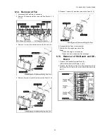
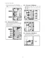
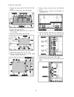
18. Remove 8 screws and then remove SC-Board.
19. Disconnect the connectors (C33, C35, SS24, SS34).
20. Remove the flexible cables from the connectors (SS53,
SS55, SS56).
21. Remove 6 screws and then remove SS-Board.
22. Remove the flexible cable from the connector (SS58).
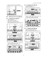
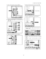
23. Remove 2 screws and then remove SS2-Board.
24. Remove the flexible cables from the connectors (C10,
C20, C26, C36).
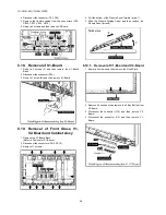
25. Remove 2 screws ( ) and then remove the S1-Board
Block.
26. Remove 3 screws ( ) and then remove the AC-Inlet
Block.
Summary of Contents for TH-50VX100U
Page 7: ...7 TH 50VX100U TH 50VX100E 3 2 Applicable signals...
Page 8: ...8 TH 50VX100U TH 50VX100E...
Page 10: ...10 TH 50VX100U TH 50VX100E 5 Operating Instructions...
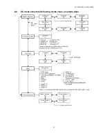
Page 15: ...15 TH 50VX100U TH 50VX100E 6 2 IIC mode structure following items value is sample data...
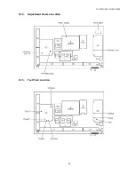
Page 33: ...33 TH 50VX100U TH 50VX100E 9 1 4 Adjustment Volume Location 9 1 5 Test Point Location...
Page 35: ...35 TH 50VX100U TH 50VX100E...
Page 37: ...37 TH 50VX100U TH 50VX100E...
Page 38: ...38 TH 50VX100U TH 50VX100E...
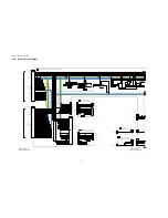
Page 47: ...47 TH 50VX100U TH 50VX100E 11 Wiring Connection Diagram 11 1 Wiring 1...
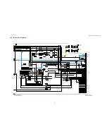
Page 48: ...48 TH 50VX100U TH 50VX100E 11 2 Wiring 2...
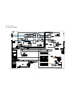
Page 49: ...49 TH 50VX100U TH 50VX100E 11 3 Wiring 3...
Page 50: ...50 TH 50VX100U TH 50VX100E...
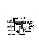
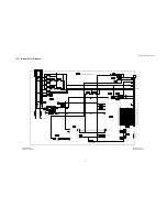
Page 51: ...TH 50VX100U TH 50VX100E 51 12 Schematic Diagram 12 1 Schematic Diagram Notes...
Page 169: ...Model No TH 50VX100U E Exploded View...
Page 170: ...Model No TH 50VX100U E Cabinet part location...
Page 171: ...Model No TH 50VX100U E Fan part location...
Page 172: ...Model No TH 50VX100U E Flat cable...
Page 173: ...Model No TH 50VX100U E Accessories...
Page 174: ...Model No TH 50VX100U E Packing 1...
Page 175: ...Model No TH 50VX100U E Packing 2...