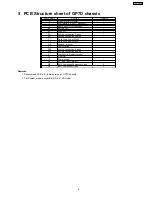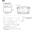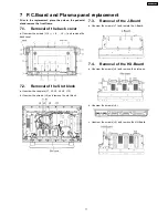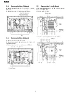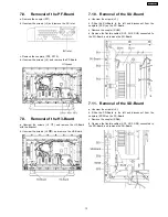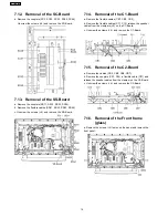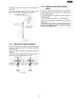
5 PCB Structure sheet of GP7D chassis
Board Name
Function
Remarks
D
Digital Signal Processor
1
J
Slot Interface & SYNC processor
1
Z
Audio out, DC-DC converter
SS
Sustain Out
1
SC
Scan out
1
SU
Sustain connection (Upper)
1
SD
Sustain connection (Lower)
1
C1
Data Drive (Lower Right)
C2
Data Drive (Lower Left)
H3
Speaker terminal
S1
Power switch
SS2
Sustain connection (Upper)
SS3
Sustain connection (Lower)
V1
Front SW. & Remote receiver
PF
Line filter
P
Power supply
1
HX
PC_type_Input terminal
HB
BNC Composite/Component Video
2
HA
BNC Component Video
2
Remarks
1. Recommend PCB´s for initial service for GP7D chassis.
2. For System model except BK, BS, EK, ES model
9
TH-37PW7BX
Summary of Contents for TH-42PWD7UY
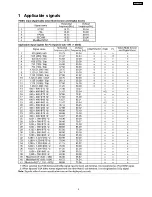
Page 5: ...1 Applicable signals 5 TH 37PW7BX ...
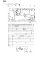
Page 16: ...8 Location of Lead Wiring 16 TH 37PW7BX ...
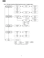
Page 22: ...10 2 IIC mode structure following items value is sample data 22 TH 37PW7BX ...
Page 31: ...13 Option Setting How to access the Option menu 31 TH 37PW7BX ...
Page 65: ...15 Schematic Diagrams 15 1 Schematic Diagram Notes TH 37PW7BX 65 ...
Page 128: ...TH 37PW7BX 128 ...
Page 129: ...16 Parts Location 129 TH 37PW7BX ...
Page 130: ...17 Packing Exploded Views 17 1 Packing Exploded Views 1 130 TH 37PW7BX ...
Page 131: ...17 2 Packing Exploded Views 2 131 TH 37PW7BX ...
Page 132: ...17 3 Packing Exploded Views 3 132 TH 37PW7BX ...
Page 135: ...19 Replacement Parts List 19 1 Replacement Parts List Notes 135 TH 37PW7BX ...


