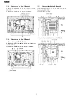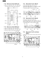
7.5. Removal of the P-Board
a. Remove the couplers (P2, P5, P7, P9, P10, P11, P12, P23,
P25, P27).
b. Unscrew the screws (×5) and remove the P-Board.
7.6. Removal of the Z-Board
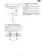
a. Remove the couplers (Z5, Z6, Z7, Z8).
b. Unscrew the screws (×4
) and remove the Z-Board with
the Z-Board Bracket.
c. Unscrew the screws (×4
) and remove the Z-Board.
7.7. Removal of the D-Board
a. Disconnect the couplers (D1, D3, D5, D25, D27) and the
flexible cables (D31, D32).
b. Remove the shield cuse.
c. Unscrew the screws (×6) and remove the D-Board.
12
TH-37PW7BX
Summary of Contents for TH-42PWD7UY
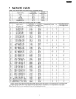
Page 5: ...1 Applicable signals 5 TH 37PW7BX ...
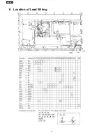
Page 16: ...8 Location of Lead Wiring 16 TH 37PW7BX ...
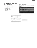
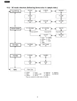
Page 22: ...10 2 IIC mode structure following items value is sample data 22 TH 37PW7BX ...
Page 31: ...13 Option Setting How to access the Option menu 31 TH 37PW7BX ...
Page 65: ...15 Schematic Diagrams 15 1 Schematic Diagram Notes TH 37PW7BX 65 ...
Page 128: ...TH 37PW7BX 128 ...
Page 129: ...16 Parts Location 129 TH 37PW7BX ...
Page 130: ...17 Packing Exploded Views 17 1 Packing Exploded Views 1 130 TH 37PW7BX ...
Page 131: ...17 2 Packing Exploded Views 2 131 TH 37PW7BX ...
Page 132: ...17 3 Packing Exploded Views 3 132 TH 37PW7BX ...
Page 135: ...19 Replacement Parts List 19 1 Replacement Parts List Notes 135 TH 37PW7BX ...


