1
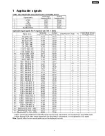
Applicable signals
5
2
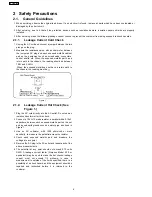
Safety Precautions
6
2.1.
General Guidelines
6
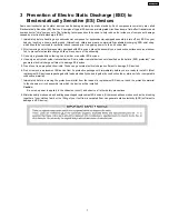
3
Prevention of Electro Static Discharge (ESD) to
Electrostatically Sensitive (ES) Devices
7
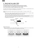
4
About lead free solder (PbF)
8
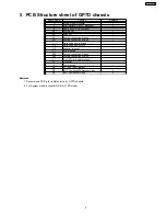
5
PCB Structure sheet of GP7D chassis
9
6
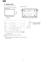
Service Hint
10
7
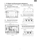
P.C.Board and Plasma panel replacement
11
7.1.
Removal of the back cover
11
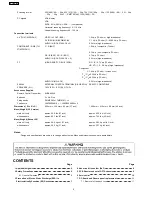
Scanning format
525 (480) / 60i
60p, 625 (575) / 50i
50p, 750 (720) / 60p
50p, 1125 (1080) / 60i
50i
24p
25p
30p
24sF .... SMPTE274M, 1250 (1080) / 50i
PC signals
VGA display
VGA
SVGA, XGA, SXGA, UXGA ..... (compressed)
Horizontal scanning frequency 15 - 110 kHz
Vertical scanning frequency 48 - 120 Hz
Connection terminals
AV (TH-37/42PWDUY)
VIDEO IN / OUT (BNC)
1.0 Vp-p (75-ohm or high impedance)
S VIDEO IN (MINI DIN 4PIN)
Y: 1 Vp-p (75-ohm), C: 0.286 Vp-p (75-ohm)
AUDIO IN (RCA PIN JACK ×2)
0.5 Vrms (high impedance)
COMPONENT / RGB (TH-
37/42PWDUY)
Y / G (BNC)
1.0 Vp-p / composite (75-ohm)
0.7 Vp-p / non-composite (75-ohm)
PB / B (BNC), PR / R (BNC)
0.7 Vp-p (75 ohm)
AUDIO IN (RCA PIN JACK × 2)
0.5 Vrms (high impedance)
PC
(HIGH-DENSITY D-SUB 15PIN)
R, G, B / 0.7 Vp-p (75-ohm)
HD, VD / 1.0 - 5.0 Vp-p (high impedance)
Component
Y:1.0 Vp-p (75-ohm : include sync)
P
B
/ C
B
:±0.35 Vp-p (75-ohm)
P
R
/ C
R
:±0.35 Vp-p (75-ohm)
AUDIO IN (M3 JACK)
0.5 Vrms (high impedance)
SERIAL
EXTERNAL CONTROL TERMINAL (D-SUB 9PIN)
RS-232C COMPATIBLE
SPEAKERS (6
W
)
16 W [8 W + 8 W] (10 % THD)
Accessories Supplied
Remote Control Transmitter
EUR646529
Batteries
2 × AA Size
Fixing bands
(TMME203 or TMME187) × 2
Ferrite core
J0KF00000018 × 1, J0KG00000054 × 2
Dimensions ( W × H × D )
920 mm × 550 mm × 89 mm (37 inch)
1,020 mm × 610 mm × 89 mm (42 inch)
Mass (Weight) (UY Version)
main unit only
approx. 54.0 lbs (37 inch)
approx. 63.9 lbs (42 inch)
with speakers
approx. 63.3 lbs (37 inch)
approx. 73.2 lbs (42 inch)
Mass (Weight) (Except UY)
main unit only
approx. 24.0 kg net (37 inch)
approx. 28.5 kg net (42 inch)
with speakers
approx. 28.2 kg (37 inch)
approx. 32.7 kg (42 inch)
Notes:
·
Design and specifications are subject to change without notice.Mass and dimensions shown are approximate.
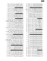
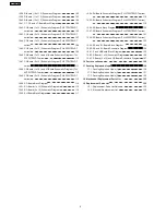
CONTENTS
Page
Page
2
TH-37PW7BX
Summary of Contents for TH-42PWD7UY
Page 5: ...1 Applicable signals 5 TH 37PW7BX ...
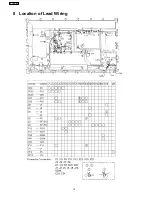
Page 16: ...8 Location of Lead Wiring 16 TH 37PW7BX ...
Page 22: ...10 2 IIC mode structure following items value is sample data 22 TH 37PW7BX ...
Page 31: ...13 Option Setting How to access the Option menu 31 TH 37PW7BX ...
Page 65: ...15 Schematic Diagrams 15 1 Schematic Diagram Notes TH 37PW7BX 65 ...
Page 128: ...TH 37PW7BX 128 ...
Page 129: ...16 Parts Location 129 TH 37PW7BX ...
Page 130: ...17 Packing Exploded Views 17 1 Packing Exploded Views 1 130 TH 37PW7BX ...
Page 131: ...17 2 Packing Exploded Views 2 131 TH 37PW7BX ...
Page 132: ...17 3 Packing Exploded Views 3 132 TH 37PW7BX ...
Page 135: ...19 Replacement Parts List 19 1 Replacement Parts List Notes 135 TH 37PW7BX ...


