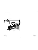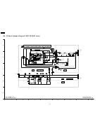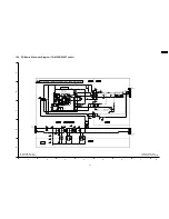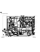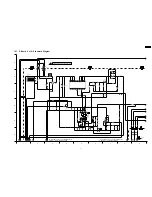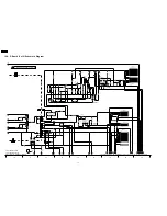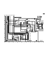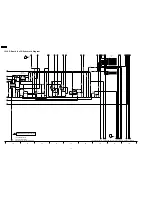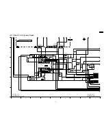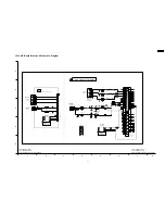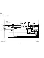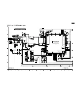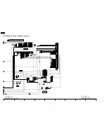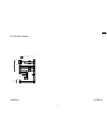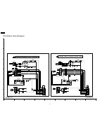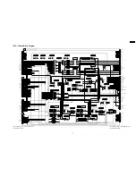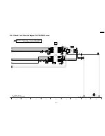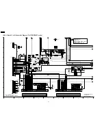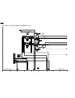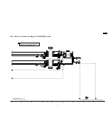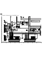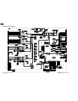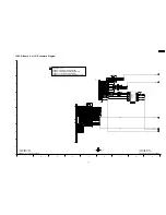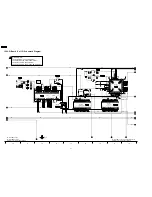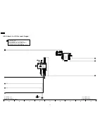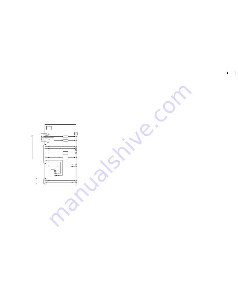
15.17. HX-Board Block Diagram
JK3513
L AMP
Q3532
R IN
L IN
14
12
13
1
2
3
15
R AMP
Q3531
13
11
5
1
3
7
9
6
5
7
VCLK
SDA
SCL
DDC EEPROM
IC3502
PC R
PC G
PC B
PC HD
PC VD
SCL
SDA
PC IN
JK3511
PC R
PC B
PC HD
PC VD
PC G
PC Ls
PC Rs
TXD
3
2
RXD
RXD
TXD
19
18
JK3509
RS-232C
REMOTE IN
HX
PC Terminal Board
HX1
9V
5V
22
21
R
L
Q3535
Q3533
Q3536
Q3534
TO J14
TH-37/42PW7 series
TH-37/42PWD7 series
HX-Board Block Diagram
TH-37/42PW7 series
TH-37/42PWD7 series
HX-Board Block Diagram
TH-37PW7BX
81
Summary of Contents for TH-42PWD7UY
Page 5: ...1 Applicable signals 5 TH 37PW7BX ...
Page 16: ...8 Location of Lead Wiring 16 TH 37PW7BX ...
Page 22: ...10 2 IIC mode structure following items value is sample data 22 TH 37PW7BX ...
Page 31: ...13 Option Setting How to access the Option menu 31 TH 37PW7BX ...
Page 65: ...15 Schematic Diagrams 15 1 Schematic Diagram Notes TH 37PW7BX 65 ...
Page 128: ...TH 37PW7BX 128 ...
Page 129: ...16 Parts Location 129 TH 37PW7BX ...
Page 130: ...17 Packing Exploded Views 17 1 Packing Exploded Views 1 130 TH 37PW7BX ...
Page 131: ...17 2 Packing Exploded Views 2 131 TH 37PW7BX ...
Page 132: ...17 3 Packing Exploded Views 3 132 TH 37PW7BX ...
Page 135: ...19 Replacement Parts List 19 1 Replacement Parts List Notes 135 TH 37PW7BX ...

