TH-103PF10WK/TK/RK
41
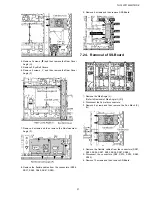
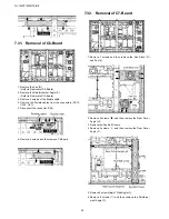
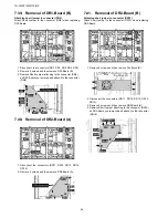
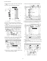
7.29. Removal of C4-Board
1. Remove the Rear Cover Angle (C).
(Refer to Removal of C3-Board)
2. Remove the Reinforcement Angle (C).
(Refer to Removal of C3-Board)
3. Remove 6 screws of the flexible cable.
4. Remove the flexible cables from the connectors (CA9,
CA10, CA11, C40, C41, C42).
5. Disconnect the connectors (C43, C44).
6. Remove 5 screws and then remove C4-Board.
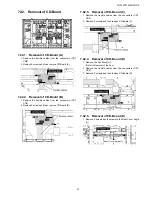
7.30. Removal of C5-Board
1. Remove the Eye Bolt and Eye Bolt Cover.
2. Remove 15 screws ( ) and then remove the Fan (C), (D)
and Fan Block (E), (F).
3. Remove 5 screws ( ) and then remove the Rear Cover
Angle (E).
4. Remove 2 screws ( ) of Side Angle (L).
5. Remove 6 screws ( ) and then remove the Reinforce-
ment Angle (E).
6. Remove 6 screws of the flexible cable.
7. Remove the flexible cables from the connectors (CA12,
CA13, CA14, C50, C51, C53).
8. Disconnect the connectors (C52, C54).
9. Remove 6 screws and then remove C5-Board.
Summary of Contents for TH-103PF10WK
Page 6: ...TH 103PF10WK TK RK 6 3 Service Navigation 3 1 Service Hint ...
Page 8: ...TH 103PF10WK TK RK 8 3 2 Applicable signals ...
Page 9: ...TH 103PF10WK TK RK 9 ...
Page 15: ...TH 103PF10WK TK RK 15 5 2 IIC mode structure following items value is sample data ...
Page 16: ...TH 103PF10WK TK RK 16 5 3 Option Setting ...
Page 57: ...TH 103PF10WK TK RK 57 Structure of replacement Plasma Panel Spare Parts ...
Page 61: ...TH 103PF10WK TK RK 61 8 1 4 Adjustment Volume Location 8 1 5 Test Point Location ...
Page 63: ...TH 103PF10WK TK RK 63 ...
Page 65: ...TH 103PF10WK TK RK 65 ...
Page 67: ...TH 103PF10WK TK RK 67 9 Block Diagram 9 1 DiagramNote ...
Page 98: ...TH 103PF10WK TK RK 98 10 8 Lead Wiring 1 ...
Page 99: ...TH 103PF10WK TK RK 99 10 9 Lead Wiring 2 ...
Page 100: ...TH 103PF10WK TK RK 100 10 10 Lead Wiring 3 ...
Page 101: ...TH 103PF10WK TK RK 101 10 11 Lead Wiring 4 ...
Page 102: ...TH 103PF10WK TK RK 102 10 12 Lead Wiring 5 ...
Page 103: ...TH 103PF10WK TK RK 103 10 13 Lead Wiring 6 ...
Page 104: ...TH 103PF10WK TK RK 104 10 14 Lead Wiring 7 ...
Page 105: ...TH 103PF10WK TK RK 105 10 15 Lead Wiring 8 ...
Page 106: ...TH 103PF10WK TK RK 106 10 16 Lead Wiring 9 ...
Page 107: ...Model No TH 103PF10WK TK RK Caution ...
Page 108: ...Model No TH 103PF10WK TK RK Exploded View ...
Page 109: ...Model No TH 103PF10WK TK RK Side Power part location ...
Page 110: ...Model No TH 103PF10WK TK RK Cabinet part location ...
Page 111: ...Model No TH 103PF10WK TK RK Fan part location ...
Page 112: ...Model No TH 103PF10WK TK RK Rear cover location ...
Page 113: ...Model No TH 103PF10WK TK RK Cable relation ...
Page 114: ...Model No TH 103PF10WK TK RK Board and Fuse ...
Page 115: ...Model No TH 103PF10WK TK RK Packing summary 1 ...
Page 116: ...Model No TH 103PF10WK TK RK Packing summary 2 ...
Page 117: ...Model No TH 103PF10WK TK RK Packing summary 3 ...
Page 118: ...Model No TH 103PF10WK TK RK Packing summary 4 ...
Page 119: ...Model No TH 103PF10WK TK RK Packing summary 5 ...
Page 120: ...Model No TH 103PF10WK TK RK Packing summary 6 ...
Page 121: ...Model No TH 103PF10WK TK RK Packing summary 7 ...


