background image

Print Parts List

file:////uspcccs0120034/...9CE/viewing/SGML_VIEW_DATA/NA/TC-P60ZT60/SVC/MTNC130589CE/mec2/en/html/print_all.htm[1/17/2014 10:10:56 AM]

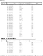
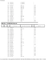
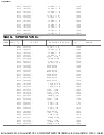
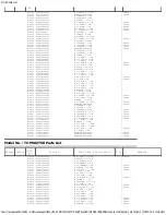
CB12

K1MY55B00001

55P  CONNECTOR

1

CB13

K1MY55B00001

55P  CONNECTOR

1

CB14

K1MY55B00001

55P  CONNECTOR

1

CB15

K1MY55B00001

55P  CONNECTOR

1

D2802A

B3AAB0000379

DIODE

1 PAVCA

D3021

DZ2J140M0L

ZENER  DIODE

1 PAVCA

D3022

DZ2J140M0L

ZENER  DIODE

1 PAVCA

D3023

DZ2J140M0L

ZENER  DIODE

1 PAVCA

D3024

DZ2J140M0L

ZENER  DIODE

1 PAVCA

D3025

DZ2J140M0L

ZENER  DIODE

1 PAVCA

D3026

DZ2J140M0L

ZENER  DIODE

1 PAVCA

D3101

K7AAAY000014

PHOTO  LINK

1 PAVCA

D4710

J0ZZB0000175

FILTER

1 PAVCA

D4713

J0ZZB0000175

FILTER

1 PAVCA

D4714

J0ZZB0000175

FILTER

1 PAVCA

D4715

J0ZZB0000175

FILTER

1 PAVCA

D4716

J0ZZB0000175

FILTER

1 PAVCA

D4717

J0ZZB0000175

FILTER

1 PAVCA

D4718

J0ZZB0000175

FILTER

1 PAVCA

D4719

J0ZZB0000175

FILTER

1 PAVCA

D4720

J0ZZB0000175

FILTER

1 PAVCA

D4721

J0ZZB0000175

FILTER

1 PAVCA

D4722

J0ZZB0000175

FILTER

1 PAVCA

D4723

DZ2J056M0L

ZENER  DIODE

1

D4724

DZ2J056M0L

ZENER  DIODE

1

D4761

DZ2J056M0L

ZENER  DIODE

1

D4773

B0JCCE000021

DIODE

1

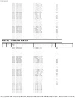
D8710

B0ACGM000001

DIODE

1 PAVCA

D8712

B0JCMD000066

ZENER  DIODE

1

D8752

DZ2J110M0L

ZENER  DIODE

1

D8753

B0ADCK000001

DIODE

1 PAVCA

D8754

DZ2J033M0L

ZENER  DIODE

1 PAVCA

D8756

DA2J10100L

DIODE

1 PAVCA

D8763

B0ACGM000001

DIODE

1 PAVCA

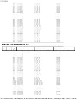
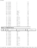
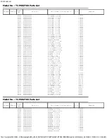
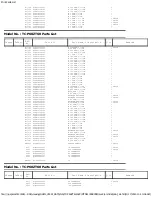
Model No. : TC-P60ZT60 Parts List

Change

Safety

Ref.

No.

Part No.

Part Name & Description

Q'ty

Remarks

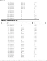
D8764

B0ACGM000001

DIODE

1 PAVCA

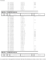
D8771

B0ADCK000001

DIODE

1 PAVCA

D8772

DZ2J068M0L

ZENER  DIODE

1 PAVCA

D8773

DZ2J068M0L

ZENER  DIODE

1 PAVCA

D9802

B0ADCK000001

DIODE

1 PAVCA

D9807

B0ADCK000001

DIODE

1 PAVCA

D16002

B0ECKP000061

DIODE

1 PAVCA

D16004

B0ECKP000061

DIODE

1 PAVCA

D16005

B0ECKP000061

DIODE

1 PAVCA

D16021

B0FCBN000003

DIODE

1 PAVCA

D16022

B0FCBN000003

DIODE

1 PAVCA

D16041

B0FACN000003

DIODE

1 PAVCA

D16043

B0FACN000003

DIODE

1 PAVCA

D16051

B0FACN000003

DIODE

1 PAVCA

D16053

B0FACN000003

DIODE

1 PAVCA

D16072

B0ECKP000055

DIODE

1

D16074

B0ECKP000055

DIODE

1

D16101

B0ECKP000061

DIODE

1 PAVCA

D16102

B0ECKP000061

DIODE

1 PAVCA

D16131

B0ECKP000055

DIODE

1

D16133

DA2J10100L

DIODE

1 PAVCA

D16134

DZ2J051M0L

ZENER  DIODE

1

D16135

DA2J10100L

DIODE

1 PAVCA

D16191

B0ECKP000055

DIODE

1

D16192

DA2J10100L

DIODE

1 PAVCA

D16196

DZ2J051M0L

ZENER  DIODE

1

D16243

DA3X103E0L

DIODE

1 PAVCA

D16251

DZ2J330M0L

ZENER  DIODE

1

D16252

DZ2J330M0L

ZENER  DIODE

1

D16254A

B3ABB0000381

LED

1 PAVCA

D16255

DA2J10100L

DIODE

1 PAVCA

D16285

DA3X102D0L

DIODE

1 PAVCA

D16315

DZ2J150M0L

ZENER  DIODE

1

D16316

B0ECKP000055

DIODE

1

D16317

B0ECHS000002

DIODE

1

D16351

DA3X102D0L

DIODE

1 PAVCA

D16362

B0FCBN000003

DIODE

1 PAVCA

D16401

B0FBCN000012

DIODE

1 PAVCA

D16407

B0JCDE000006

DIODE

1 PAVCA

D16411

DA2J10100L

DIODE

1 PAVCA

D16413

DA2J10100L

DIODE

1 PAVCA

D16421

B0FCBN000003

DIODE

1 PAVCA

D16422

B0FCBN000003

DIODE

1 PAVCA

D16430

B0ECKP000061

DIODE

1 PAVCA

D16432

B0ECKP000055

DIODE

1

D16462

B0FACN000003

DIODE

1 PAVCA

D16463

B0FACN000003

DIODE

1 PAVCA

D16473

DA2J10100L

DIODE

1 PAVCA

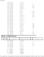
D16477

DA2J10100L

DIODE

1 PAVCA

D16481

B0FACN000003

DIODE

1 PAVCA

D16482

B0FACN000003

DIODE

1 PAVCA

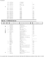
D16506

DZ2J051M0L

ZENER  DIODE

1

D16534

DZ2J051M0L

ZENER  DIODE

1

Summary of Contents for TCP60ZT60

Page 1: ...p Plasma HDTV Model No TC P60ZT60 GPF16DU Chassis For detailed troubleshooting information and circuit explanations refer to the QSM Service Hints Troubleshooting Information TI and Seminar Training Manual Technical Guide TG documents posted on the TSN web site For information about this model type TC P2013 in the model box under Direct Search ...

Page 2: ...ce tool mode 11 6 4 Hotel mode 12 6 5 Data Copy by USB Memory 13 7 Troubleshooting Guide 16 8 Service Fixture Tools 17 8 1 SC jig 17 9 Disassembly and Assembly Instructions 18 9 1 Disassembly Flow Chart for the Unit 18 9 2 Disassembly Procedure for the Unit 19 10 Measurements and Adjustments 26 10 1 Adjustment 26 11 Block Diagram 29 11 1 Main Block Diagram 29 11 2 Block 1 4 Diagram 30 11 3 Block 2...

Page 3: ...he jumpered AC plug and each exposed metallic cabinet part on the equipment such as screwheads connectors control shafts etc When the exposed metallic part has a return path to the chassis the reading should be between 1Mohm and 5 2Mohm When the exposed metal does not have a return path to the chassis the reading must be 1 1 2 Leakage Current Hot Check See Figure 1 1 Plug the AC cord directly into...

Page 4: ... of the assembly 3 Use only a grounded tip soldering iron to solder or unsolder ES devices 4 Use only an anti static solder removal device Some solder removal devices not classified as anti static ESD protected can generate electrical charge sufficient to damage ES devices 5 Do not use freon propelled chemicals These can generate electrical charges sufficient to damage ES devices 6 Do not remove a...

Page 5: ...ee solder has a higher melting point than standard solder Typically the melting point is 50 70 F 30 40 C higher Please use a high temperature soldering iron and set it to 700 20 F 370 10 C Pb free solder will tend to splash when heated too high about 1100 F or 600 C If you must use Pb solder please completely remove all of the Pb free solder on the pins or solder area before applying Pb solder If ...

Page 6: ... should be exchanged for service A Main AV input processing K Remote receiver Power LED C A T S sensor C1 Data Driver Lower Right C2 Data Driver Lower Center C3 Data Driver Lower Left SC Scan Drive SS Sustain Drive SS2 Sustain out Lower SU Scan out Upper Non serviceable SU Board should be exchanged for service SD Scan out Lower Non serviceable SD Board should be exchanged for service ...

Page 7: ...DIO R HDMI IN 1 2 3 TYPE A Connector supports HDAVI Control 5 function USB 1 2 3 USB2 0 Type A connector DC 5V Max 500 mA DIGITAL AUDIO OUT PCM Dolby Digital Fiber Optic OTHERS SD card slot ETHERNET 10BASE T 100BASE TX Dimensions W H D Including pedestal 55 3 inch 36 3 inch 12 2 inch 1 404 mm 921 mm 308 mm TV Set only 55 3 inch 32 6 inch 1 9 inch 1 404 mm 828 mm 47 mm Mass Including pedestal 97 0 ...

Page 8: ...tored in both Main IC IC8000 and NAND Flash IC8900 5 1 2 Replacement of ICs When Main IC is replaced NAND Flash should be also replaced with new one the same time When NAND Flash is replaced Main IC is not necessary to be replaced the same time After the replacement of IC SELF CHECK should be done to generate the final KEY data How to SELF CHECK While pressing VOLUME button on the main unit press ...

Page 9: ...tered when 3D signal input Input 2D signal to enter Service Mode 6 1 2 Key command 1 button Main items Selection in forward direction 2 button Main items Selection in reverse direction 3 button Sub items Selection in forward direction 4 button Sub items Selection in reverse direction VOL button Value of sub items change in forward direction in reverse direction 6 1 3 How to exit Switch off the pow...

Page 10: ...TBY SET 00 EMERGENCY ON CLK MODE 00 CLOCK 000 EDID CLK SHIGH MIRROR 00 See Option Mirror VSUS LOW See Vsus selection AGING ALL WHITE Built in test patterns can be displayed MIDDLE BLUE WITH MAGENTA OUTSIDE FRAME MIDDLE STEP GREEN MIDDLE STEP RED LOW STEP WHITE ALL BLUE ALL GREEN ALL RED WHITE DIAGONAL STRIPE RED DIAGONAL STRIPE GREEN DIAGONAL STRIPE BLUE DIAGONAL STRIPE A ZONE B ZONE 1 WINDOW COLO...

Page 11: ...tion From left side Last SOS before Last three occurrence before 2nd occurrence after shipment 1st occurrence after shipment This indication except 2nd and 1st occurrence after shipment will be cleared by Self check indication and forced to factory shipment setting 6 3 3 POWER ON TIME COUNT Note To display TIME COUNT menu highlight position then press MUTE for 3 sec Time Cumulative power on time i...

Page 12: ...h time power is switched on Selection RF HDMI1 HDMI2 HDMI3 AV Off give priority to a last memory Channel Select channel when input signal is RF Set the channel each time power is switched on Selection Any channel number or means the channel when turns off Volume Adjust the volume when each time power is switched on Range 0 to 100 Vol Max Adjust maximum volume Range 0 to 100 OSD Ctrl Restrict the O...

Page 13: ...then copy to other TVs 6 5 2 Preparation Make pwd file as startup file for a or b in a empty USB Memory 1 Insert a empty USB Memory to your PC 2 Right click a blank area in a USB Memory window point to New and then click text document A new file is created by default New Text Document txt 3 Right click the new text document that you just created and select rename and then change the name and exten...

Page 14: ...llowing password for a or b by using remote control a For Board replacement 2770 b For Hotel 4850 Data will be copied from TV set to USB Memory It takes around 2 to 6 minutes maximum for copying 4 After the completion of copying to USB Memory remove USB Memory from TV set 5 Turn off the TV set Note Following new folder will be created in USB Memory for data from TV set a For Board replacement user...

Page 15: ...ent 2771 b For Hotel 4851 Data will be copied from USB Memory to TV set 4 After the completion of copying to USB Memory remove USB Memory from TV set a For Board replacement Data will be deleted after copying Limited one copy b For Hotel Data will not be deleted and can be used for other TVs 5 Turn off the TV set Note 1 Depending on the failure of boards function of Data copy for board replacement...

Page 16: ...rmation and circuit explanations refer to the QSM Service Hints Troubleshooting Information TI and Seminar Training Manual Technical Guide TG documents posted on the TSN web site For information about this model type TC P2013 in the model box under Direct Search ...

Page 17: ...lly Note The board will be damaged if all connector is not removed for example remove connector only for SU board and stay connecting with SD board The board will be damaged 3 Connect SC jig to connector SC50 at left bottom side of SC board 4 Turn on the TV Display Unit and confirm the power LED blinking LED blinking Possible cause of failure is in SC board No LED blinking Lighting or no lighting ...

Page 18: ...18 9 Disassembly and Assembly Instructions 9 1 Disassembly Flow Chart for the Unit This is a disassembly chart When assembling perform this chart conversely ...

Page 19: ...stal stand 9 2 2 Remove the Bottom cover 1 Remove the screws 4 and remove the Bottom cover 9 2 3 Remove the AC cord clamper B 1 Remove the screws 2 and remove the AC cord clamper B 9 2 4 Remove the Wi Fi module 1 Remove the screw 1 and remove the Wi Fi module 9 2 5 Remove the Bluetooth module 1 Remove the screw 1 and remove the Dongle cover 2 Remove the Pin guides 2 and disconnect the BT connector...

Page 20: ...and P58 3 Remove the screws 6 and remove the P MAIN Board 9 2 9 Remove the P SUB Board Caution To remove P C B wait 1 minute after power was off for discharge from electrolysis capacitors 1 Unlock the cable clampers and the tapes to free the cables 2 Disconnect the connectors P51 P55 and P57 3 Remove the screws 4 and remove the P SUB Board 9 2 10 Remove the A Board 1 Unlock the hooks and the tapes...

Page 21: ... Remove the Speaker SQs 1 Unlock the hooks and the tapes to free the cables 2 Disconnect the Relay connector 3 Remove the screws 2 each and remove the Speaker SQs L R 9 2 13 Remove the Woofer 1 Unlock the hooks and the tapes to free the cables 2 Disconnect the Relay connector 3 Remove the screws 3 and remove the Woofer 9 2 14 Remove the Fan 1 Unlock the hooks and the tapes to free the cables 2 Rem...

Page 22: ...sconnect the flexible cable SU11 SD11 and the bridge connectors SC42 SD42 and SC46 SD46 3 Remove the screws 3 2 and remove the SD Board 9 2 17 Remove the SC Board 1 Unlock the tapes to free the cables 2 Disconnect the connector SC2 3 Disconnect the flexible cable SC20 4 Remove the screws 9 and remove the SC Board 9 2 18 Work instructions for the Rubber sheet for SC Board 1 Rubber sheets are put be...

Page 23: ...ets are put between the board and rear cover for EMC requirement and heat radiation Confirm rubber sheets were placed at each portion when assembling as shown in figure 9 2 21 Remove the SS2 Board 1 Disconnect the flexible cable SS65 and SS67 2 Remove the screws 2 and remove the SS2 Board 9 2 22 Remove the USB cable A WiFi 1 Remove the screw 1 2 Remove the USB cable A WiFi 9 2 23 Remove the Metal ...

Page 24: ...onnector K10 3 Remove the claw 1 and remove the K Board 4 Remove the LED panel 9 2 26 Remove the Cabinet assy from the Plasma panel section 1 Remove the Plasma panel section from the servicing stand and lay on a flat surface such as a table covered by a soft cloth with the Plasma panel surface facing downward 2 Remove the screws 21 3 Remove the Cabinet assy from the Plasma panel section ...

Page 25: ...tors C24 and C28 4 Remove the screws 6 and remove the C2 Board 9 2 30 Remove the C3 Board 1 Disconnect the flexible cables CB12 CB13 CB14 and CB15 2 Disconnect the flexible cables C31 and C36 3 Remove the screws 4 and remove the C3 Board 9 2 31 Replace the Plasma panel Caution Remove the Plasma panel section from the servicing stand and lay on a flat surface such as a table covered by a soft cloth...

Page 26: ...ress 5 button to display the On Screen Display 3 Press VOL button to set to LOW 4 In LOW setting a If no several dead pixel is visible remarkably in white pattern press 3 button to go to CONF stage b If the several dead pixels are visible remarkably in white pattern Set to HIGH by press VOL button Press 3 button to go to CONF stage if the symptom is improved 5 Press OK button in CONF stage to stor...

Page 27: ...s the values written in table1 5 INNER PATTERN is displayed by using 5 key by using 5 key in the remote controller 6 Select G CUTOFF by using the 3 and 4 key in the remote controller and set the value to 80 by using the volume and key Also B CUTOFF and R CUTOFF set to 80 7 Set G DRIVE value to the initial data ex D0 8 Set the color analyzer and adjust color point to the values written in table1 by...

Page 28: ...28 ...

Page 29: ...MES LED 7TIMES P5V SOS8_SS R_LED_ON P15V F15V P5V SOS6_SC1 A32 SPI FLASH IIC1 P15V USB3 HDD F15V SUB1 1V DCDC15V USB1 VDDSD 18V33V MAIN_FAN_ON SUB1 5V F15V WiFi IF_P N STB1 1V FAN_SOS DIGITAL SUB1 1V SUB5V FAN CONT LVDS I F SUB3 3V STB3 3V SUB3 3V_SENSE USB0 2_DP DN P3 3V FAN ON V YPbPr RGB MAIN AV INPUT PROCESSING USB2 SPEAKER R KEYSCAN USB HUB WOOFER AUDIO OUT L VIDEO DATA C A T S_SENSOR SUB3 3V...

Page 30: ...SBI0 SBO0 JK8600 F15V IC8101 PANEL_MAIN_ON TEMP SENSOR USB1 HDMI_CEC_ PULL_ON WOL3 3V STB5V_SWON LAN CON I F 12MHz RX1 IC8601 ETHERNET TUNER_SUB_ON G_XRST HDMI_CEC USB HUB JK8602A 1 8V P_XRST JK4703C JK8605 IC8715 IC8606 WiFi PDP_DRVRST VBUS2 JK8601C FE_XRST_T IFAGC JK8603D USB2 LOSD_VIN MAIN AV INPUT PROCESSING HDMI1 IC8603 LOSD_VIN AUDIO AMP2 P15V_DET RX0 P_XRST HDMI_5V_DET0 DISPEN 1 1V G_XRST D...

Page 31: ...IC9504 SOS_DCC IC9300 GCX1 5V VIDEO DATA 54 SC_UHZ A32 POWER DRVRST_ OUT P3 3V DCDCEN 55 1 5V OFF_FLAG 6 SCAN DATA BUFFER X0 VIDEO DATA 3 3V 1 LVDS DATA UHZ 1 1V P_S0 DCDC_CTL P3 3V 7 P15V STB3 3V 5 DCDCEN FFC_OFF_DET SOS_DCC REMOTE_IN IC9402 4 1 A33 R_LED_ON LVDS DATA DRVRST 3 PLASMA AI CPG H V Sync Control Sub Filed Processor REMOTE RECEIVER USB_DP DN P15V P15V LVDS TX DTV15V LVDS DATA 1 2V 5 PO...

Page 32: ...LTER EV5V P_S0 SC2 C24 3 PHOTO COUPLER OVP LVP 2 STB5V_SW_ON PANEL_MAIN_ON T901 L FEED BACK ERROR DET FET SW VSUS CONVERTER 1 P 15V 7 AC DETECTION PROTECTION OVP LVP OCP SWITCH CONTROL RELAY CONTROL ERROR DET N P11 LV CONVERTER OCP FEED BACK 1 P2 5 A6 15 FET SW T501 FEED BACK AC CORD 13 F15V Vsus STB5V REG LVP 11 TUNER_SUB_ON P9 PHOTO COUPLER POWER FACTOR CONTROL P51 P52 P57 P58 P55 P56 LVP OVP LV...

Page 33: ...51 Q16052 9 8 8 VSCN GEN P5V IC16521 SS 33 SUSOUT Q16003 Q16004 IC16784 85 13 IC16241 BUFFER VSCN F SS 11 SS 62 SU 11 CLK Reference Voltage Ve 150V 2 LED G Q16660 ERM SD 11 SC Q16021 Q16023 Q16024 1 CSL IPD CIRCUIT 2 IPD CIRCUIT PLASMA PANEL BUFFER 2 SUSTAIN L 13 D16713 SIU 1 VFG SOS8_SS UHZ IC14804 06 16 CELR SD USH SCAN OUT UPPER SCAN DRIVE SHUNT REG BUFFER SCAN CONTROL 2 SS 64 VFO BUFFER VAD GE...

Page 34: ...34 ...

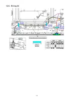
Page 35: ...Diagram 12 1 Caution statement Caution Please confirm that all flexible cables are assembled correctly Also make sure that they are locked in the connectors Verify by giving the flexible cables a very slight pull 12 2 Wiring 1 ...

Page 36: ...36 12 3 Wiring 2 ...

Page 37: ...37 12 4 Wiring 3 12 5 Wiring 4 ...

Page 38: ...38 12 6 Wiring 5 ...

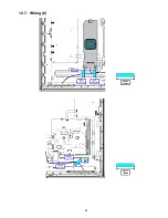
Page 39: ...39 12 7 Wiring 6 ...

Page 40: ...40 12 8 Wiring 7 ...

Page 41: ...Model No TC P60ZT60 Exploded View 1 1 3 ...

Page 42: ...Model No TC P60ZT60 Exploded View 2 2 3 ...

Page 43: ...Model No TC P60ZT60 Accessories 3 3 ...

Page 44: ...A834 C 39 pF 50 V 1 PAVCA C0905 F1G1H390A834 C 39 pF 50 V 1 PAVCA C2000 F1G1E103A059 C 0 01UF 25V 1 PAVCA C2001 F1J1A106A043 C 10UF 10V 1 PAVCA C2002 F1J1E105A287 C 1UF 25V 1 PAVCA C2006 F1G1C104A077 C 0 1UF 16V 1 PAVCA C2010 F1G1A105A047 C 1UF 10V 1 PAVCA C2013 F1G1E103A059 C 0 01UF 25V 1 PAVCA C2014 F1G1E103A059 C 0 01UF 25V 1 PAVCA C2018 F1G1H1020008 C 1000PF 50V 1 PAVCA C2019 F1G1E103A059 C 0 ...

Page 45: ...0UF 10V 1 PAVCA C8003 F1J1A106A043 C 10UF 10V 1 PAVCA C8006 F1G1C104A077 C 0 1UF 16V 1 PAVCA C8007 F1G1C104A077 C 0 1UF 16V 1 PAVCA C8015 F1J0G2260001 C 22 UF 4 V 1 PAVCA C8017 F1J0G2260001 C 22 UF 4 V 1 PAVCA C8018 F1G1A105A047 C 1UF 10V 1 PAVCA Model No TC P60ZT60 Parts List Change Safety Ref No Part No Part Name Description Q ty Remarks C8020 F1G1C104A077 C 0 1UF 16V 1 PAVCA C8021 F1G1H101A834 ...

Page 46: ... PAVCA C8617 F1G1C1030008 C 0 01UF 16V 1 PAVCA C8619 F1G1C104A077 C 0 1UF 16V 1 PAVCA C8620 F1G1C104A077 C 0 1UF 16V 1 PAVCA C8627 F1G1C104A077 C 0 1UF 16V 1 PAVCA C8628 F1K0J226A049 C 22UF 6 3V 1 C8629 F1K0J226A049 C 22UF 6 3V 1 C8632 F1J1A106A043 C 10UF 10V 1 PAVCA C8633 F1G1C104A077 C 0 1UF 16V 1 PAVCA C8635 F1J1A106A043 C 10UF 10V 1 PAVCA C8636 F1G1C104A077 C 0 1UF 16V 1 PAVCA C8637 F1J1A106A0...

Page 47: ...C9302 F1G1H180A834 C 18PF 50V 1 PAVCA C9308 F1G1C104A077 C 0 1UF 16V 1 PAVCA C9309 F1G1A105A047 C 1UF 10V 1 PAVCA C9311 F1G1C104A077 C 0 1UF 16V 1 PAVCA C9312 F1J1A106A043 C 10UF 10V 1 PAVCA C9317 F1G1A105A047 C 1UF 10V 1 PAVCA C9318 F1G1A105A047 C 1UF 10V 1 PAVCA C9319 F1G1A105A047 C 1UF 10V 1 PAVCA C9320 F1G1A105A047 C 1UF 10V 1 PAVCA C9321 F1G1A105A047 C 1UF 10V 1 PAVCA C9322 F1G1A105A047 C 1UF...

Page 48: ...CA Model No TC P60ZT60 Parts List Change Safety Ref No Part No Part Name Description Q ty Remarks C9555 F1G1C104A077 C 0 1UF 16V 1 PAVCA C9556 F1J1A106A043 C 10UF 10V 1 PAVCA C9557 F1G1C104A077 C 0 1UF 16V 1 PAVCA C9558 F1G1A105A047 C 1UF 10V 1 PAVCA C9559 F1G1C104A077 C 0 1UF 16V 1 PAVCA C9560 F1G1A105A047 C 1UF 10V 1 PAVCA C9561 F1G1C104A077 C 0 1UF 16V 1 PAVCA C9564 F1G1C104A077 C 0 1UF 16V 1 P...

Page 49: ... C16317 ECJ1VB1A105K C 1UF 10V 1 C16318 F1J1H104A717 C 0 1UF 50V 1 C16319 F1J1H104A717 C 0 1UF 50V 1 C16328 F2A2C1010028 E 100UF 160V 1 C16330 F0C2E105A286 C 1 UF 250 V 1 PAVCA C16351 F1H1H104A970 C 0 1UF 50V 1 C16352 F1H1H104A970 C 0 1UF 50V 1 C16362 F1L2J562A021 C 5600PF 630V 1 PAVCA C16401 F1L2J562A021 C 5600PF 630V 1 PAVCA C16402 F1L2J562A021 C 5600PF 630V 1 PAVCA C16411 F2A2T3010002 E 300UF M...

Page 50: ...9 C 1UF 25V 1 C16903 F1K2J102A058 C 1000PF J 630V 1 PAVCA C16905 F1K2J331A042 C 330PF 630V 1 PAVCA C16907 F1K2J2210003 C 220PF 630V 1 PAVCA C16908 F1L2J472A021 C 4700PF 630V 1 PAVCA C16910 F1K2J681A039 C 680PF 630V 1 PAVCA C16912 F1K2J681A039 C 680PF 630V 1 PAVCA C17101 F1H1A105A099 C 1UF 10V 1 PAVCA C17102 F1H1A105A099 C 1UF 10V 1 PAVCA C17103 F1H1A105A099 C 1UF 10V 1 PAVCA C17107 F1L2E224A028 C ...

Page 51: ...A D8772 DZ2J068M0L ZENER DIODE 1 PAVCA D8773 DZ2J068M0L ZENER DIODE 1 PAVCA D9802 B0ADCK000001 DIODE 1 PAVCA D9807 B0ADCK000001 DIODE 1 PAVCA D16002 B0ECKP000061 DIODE 1 PAVCA D16004 B0ECKP000061 DIODE 1 PAVCA D16005 B0ECKP000061 DIODE 1 PAVCA D16021 B0FCBN000003 DIODE 1 PAVCA D16022 B0FCBN000003 DIODE 1 PAVCA D16041 B0FACN000003 DIODE 1 PAVCA D16043 B0FACN000003 DIODE 1 PAVCA D16051 B0FACN000003 ...

Page 52: ...A HS16662 K4AZ02D00004 TERMINAL 1 PAVCA HS16663 K4AZ02D00004 TERMINAL 1 PAVCA IC2001 C1ZBZ0004368 IC 1 IC4900 C1AB00003800 IC 1 PAVCA IC4901 C1AB00003984 IC 1 PAVCA IC5000 AN34044AAVF IC 1 IC5704 C0DBEYY00102 IC 1 PAVCA IC8000 MN2WS02351B IC 1 PAVCA IC8100 C0DBAYY01646 IC 1 PAVCA IC8101 C0DBAYY01284 IC 1 PAVCA IC8200 C3ABUY000035 IC 1 PAVCA IC8201 C3ABUY000035 IC 1 PAVCA IC8202 C3ABUY000035 IC 1 P...

Page 53: ...CA L8002 D0GAR00J0005 M 0 OHM 1 16W 1 PAVCA L8004 D0GBR00J0004 M 0 OHM J 1 10W 1 PAVCA L8005 D0GAR00J0005 M 0 OHM 1 16W 1 PAVCA L8006 D0GAR00J0005 M 0 OHM 1 16W 1 PAVCA L8007 D0GAR00J0005 M 0 OHM 1 16W 1 PAVCA L8008 D0GAR00J0005 M 0 OHM 1 16W 1 PAVCA L8009 J0JYC0000464 FILTER 1 PAVCA L8010 D0GAR00J0005 M 0 OHM 1 16W 1 PAVCA L8011 D0GAR00J0005 M 0 OHM 1 16W 1 PAVCA L8012 D0GAR00J0005 M 0 OHM 1 16W ...

Page 54: ...101 B1CFRD000100 FET 1 PAVCA Q8771 B1HFCEA00001 TRANSISTOR 1 Q9201 B1HFCEA00001 TRANSISTOR 1 Q9500 B1CFRD000100 FET 1 PAVCA Q9501 B1CFRD000100 FET 1 PAVCA Q16003 B1JADN000013 TRANSISTOR 1 PAVCA Q16004 B1JADN000013 TRANSISTOR 1 PAVCA Q16021 B1JBDN000005 TRANSISTOR 1 PAVCA Q16023 B1JBDN000005 TRANSISTOR 1 PAVCA Q16024 B1JBDN000005 TRANSISTOR 1 PAVCA Q16041 B1JADN000014 TRANSISTOR 1 PAVCA Q16043 B1JA...

Page 55: ...6W 1 PAVCA R1357 D0GA103JA039 M10KOHM J 1 16 W 1 PAVCA R1358 D0GA103JA039 M10KOHM J 1 16 W 1 PAVCA R1359 D0GA103JA039 M10KOHM J 1 16 W 1 PAVCA R1360 D0GA103JA039 M10KOHM J 1 16 W 1 PAVCA R1361 D0GA103JA039 M10KOHM J 1 16 W 1 PAVCA R1362 D0GA103JA039 M10KOHM J 1 16 W 1 PAVCA R1365 D0GA103JA039 M10KOHM J 1 16 W 1 PAVCA R1366 D0GA103JA039 M10KOHM J 1 16 W 1 PAVCA R1373 D0GA103JA039 M10KOHM J 1 16 W 1...

Page 56: ...0GA103JA039 M10KOHM J 1 16 W 1 PAVCA R4752 D0GA103JA039 M10KOHM J 1 16 W 1 PAVCA R4753 D0GA103JA039 M10KOHM J 1 16 W 1 PAVCA R4755 D0GA102JA039 M1KOHM J 1 16 W 1 PAVCA R4757 D0GA473JA039 M 47KOHM J 1 16W 1 PAVCA R4758 D0GA473JA039 M 47KOHM J 1 16W 1 PAVCA R4759 D0GA680JA023 M 68 OHM J 1 16W 1 PAVCA R4760 D0GA680JA023 M 68 OHM J 1 16W 1 PAVCA Model No TC P60ZT60 Parts List Change Safety Ref No Part...

Page 57: ...8304 D1BA6201A023 M 6 2 KOHM F 1 16 W 1 PAVCA R8305 D1H82204A042 NETWORK RESISTER 1 PAVCA R8306 D1H82204A042 NETWORK RESISTER 1 PAVCA R8307 D1H82204A042 NETWORK RESISTER 1 PAVCA R8308 D1H82204A042 NETWORK RESISTER 1 PAVCA R8309 D1H82204A042 NETWORK RESISTER 1 PAVCA R8310 D1H82204A042 NETWORK RESISTER 1 PAVCA R8311 D0GA220JA023 M22 OHM J 1 16 W 1 PAVCA R8313 D1H82204A042 NETWORK RESISTER 1 PAVCA R8...

Page 58: ...714 D1BA4702A023 M 47 KOHM F 1 16 W 1 PAVCA R8715 D1BA4301A023 M 4 3 KOHM F 1 16 W 1 PAVCA R8716 D0GAR00J0005 M 0 OHM 1 16W 1 PAVCA R8717 D1BA1501A023 M 1 5 KOHM F 1 16 W 1 PAVCA R8720 D0GA472JA023 M 4 7KOHM J 1 16W 1 PAVCA R8721 D0GF471JA048 M 470 OHM J 1 4 W 1 PAVCA R8723 D0GA472JA023 M 4 7KOHM J 1 16W 1 PAVCA R8724 D0GA471JA023 M 470OHM J 1 16W 1 R8725 D0GA473JA039 M 47KOHM J 1 16W 1 PAVCA R872...

Page 59: ...81034A042 NETWORK RESISTER 1 PAVCA R9401 D1H81034A042 NETWORK RESISTER 1 PAVCA R9402 D1H81034A042 NETWORK RESISTER 1 PAVCA Model No TC P60ZT60 Parts List Change Safety Ref No Part No Part Name Description Q ty Remarks R9403 D0GA103JA039 M10KOHM J 1 16 W 1 PAVCA R9405 D1H86804A042 NETWORK RESISTER 1 PAVCA R9410 D1H81034A042 NETWORK RESISTER 1 PAVCA R9411 D0GA103JA039 M10KOHM J 1 16 W 1 PAVCA R9413 ...

Page 60: ...J 1 16 W 1 PAVCA R9943 D0GA102JA039 M1KOHM J 1 16 W 1 PAVCA R9946 D0GA103JA039 M10KOHM J 1 16 W 1 PAVCA R16003 D0GF7R5JA047 M 7 5 OHM J 1 3W 1 R16004 D0GF7R5JA047 M 7 5 OHM J 1 3W 1 R16021 D0GF7R5JA047 M 7 5 OHM J 1 3W 1 R16023 D0GF7R5JA047 M 7 5 OHM J 1 3W 1 R16024 D0GF7R5JA047 M 7 5 OHM J 1 3W 1 R16031 D0GF473JA048 M 47KOHM J 1 3W 1 R16032 D0GF473JA048 M 47KOHM J 1 3W 1 R16041 D0GF5R6JA047 M 5 6...

Page 61: ... OHM J 1 16W 1 R16472 D0GA222JA023 M 2 2KOHM J 1 16W 1 PAVCA R16473 D0GD561JA052 M 560 OHM J 1 8W 1 PAVCA R16474 D0GA102JA023 M1KOHM J 1 16 W 1 R16475 D0GA472JA023 M 4 7KOHM J 1 16W 1 PAVCA R16476 D1H82224A041 NETWORK RESISTER 1 PAVCA R16478 D0GD203JA052 M 20KOHM J 1 8W 1 R16479 D0GD100JA052 M 10 OHM J 1 8W 1 R16480 D0GD104JA052 M 100KOHM J 1 8W 1 PAVCA R16490 D1BD1203A147 M 120KOHM F 1 8 W 1 PAVC...

Page 62: ...A R16835 D0GF683JA048 M 68 KOHM J 1 4W 1 PAVCA R16836 D0GF683JA048 M 68 KOHM J 1 4W 1 PAVCA R16841 D0GA472JA023 M 4 7KOHM J 1 16W 1 PAVCA R16842 D0GD102JA052 M 1 0KOHM J 1 8W 1 R16844 ERA6YEB242 M 2 4KOHM B 1 10W 1 R16845 D1BD6042A147 M60 4KOHM D 1 10W 1 PAVCA R16846 D1BD6042A147 M60 4KOHM D 1 10W 1 PAVCA R16847 D1BD6492A147 M 64 9KOHM F 1 8W 1 PAVCA R16851 D0GA474JA023 M470KOHM J 0 063W 1 R16852 ...

Page 63: ...47 M 1 OHM J 1 3W 1 R17261 D0GD224JA052 M 220KOHM J 1 8W 1 PAVCA R17263 D0GB681JA065 M 680 OHM J 1 10W 1 R17264 D0GB681JA065 M 680 OHM J 1 10W 1 R17284 D0GB331JA065 M330 OHM J 1 10W 1 R17286 D0GB470JA065 M 47 OHM J 1 10W 1 R17287 D1H84704A041 NETWORK RESISTER 1 PAVCA R17289 D1H84704A041 NETWORK RESISTER 1 PAVCA R17292 D0GB470JA065 M 47 OHM J 1 10W 1 R17295 D1H86814A041 NETWORK RESISTER 1 PAVCA R17...

Page 64: ...PAVCA 3 L0EYAA000035 WOOFER MIDDLE 1 PAVCA 4 L6FAYYYG0016 FAN 2 PAVCA 5 MD60F16C9A PLASMA DISPLAY PANEL 1 PAVCA 43 N2QAYB000862 REMOTE CONTROL 1 PAVCA 44 N2QBYB000028 TOUCH PAD REMOTE CONTROL 1 PAVCA 6 N5HBZ0000101 WIFI MODULE DONGLE 1 PAVCA 7 N5HZZ0000130 BLUETOOTH MODULE DONGLE 1 PAVCA 45 N5ZZ00000287 ACTIVE 3D EYEWEAR 2 PAVCA 8 TBL5ZX07141 PEDESTAL ASSY 1 PAVCA TEWB633 GASKET L15 W7 T2 RCA 1 PA...

Page 65: ...D METAL 1 PAVCA TUX5ZE0221 BOTTOM SHIELD METAL 1 PAVCA 24 TXAUC01UVUU AC INLET WITH CABLE 1 PAVCA 25 TXFBL5Z0135 PEDESTAL STAND METAL ASSY 1 PAVCA 26 TXFBL5Z0138 PEDESTAL STAND METAL COVER ASSY 1 PAVCA 27 TXFKU4713SER REAR COVER 1 PAVCA 48 TXFPZ5Z0001 BOOKLET 1 PAVCA TXJ A1UEUU WIRE A1 K10 BT 1 PAVCA TXJA12UVUU SPEAKER LEAD A12 SPR SPL WOOFER 1 PAVCA XTV3 8GFJK SCREW BT_COVER 1 1 XYN3 F6FJ SCREW C...

Reviews: