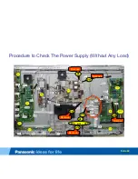
Procedure to Check The Power Supply (Without Any Load)
The Power Supply can be tested without any load by removing several connectors from the P and A boards.
Remove the following connectors from the P board:
P2, P11, and P35.
Remove the following connectors from the A board :
A11, A12, A20, A31, A32, A14, and A40.
Procedure:
1.
Plug in the TV. The relays from the P board should click. (
Note:
if a second click is heard approximately 10~15 seconds
after the 1
st
click, the F15V is confirmed to be present.)
2.
Turn the power on. (
Note:
The power LED should turn on and the fans should be running. If this is the case, measure the
Vsus and Vda.)
Vsus can be measured on pin 1 of connector P2 or P11.
Vda can be measured on pin 1 of connector P35.
3.
If these voltages are OK, then the power supply is OK. (
Note:
The TV won’t turn on if there is a short circuit on the
P15V.)
Note:
If there is a short circuit on the Vsus or Vda lines while this test is conducted;
•
The SOS4_PS is not triggered. Pin 4 of connector P6 stays low. (
Note:
The PS SOS only monitors over-voltage conditions.
•
The TV will still turn on without Vsus or Vda.
•
The fans will continue to run.
Caution:
Do not allow the TV to run for more than 30 seconds when isolating the power supply.
Slide 81
Summary of Contents for TC-PXXGT30
Page 5: ...Features Slide 5 ...
Page 6: ...2011 Premium 3D PDP Line up And Feature Comparison Slide 6 ...
Page 9: ...Connection Mini Adapters Slide 9 ...
Page 10: ...Boards Layout TC P55VT30 Slide 10 ...
Page 13: ...2011 PDP Extension Cable list GT30 series Model TC P50 55 60 65 GT30 Slide 13 ...
Page 14: ...2011 PDP Extension Cable for A board GT30 series Slide 14 ...
Page 15: ...2011 PDP Extension Cable for P board GT30 series Slide 15 ...
Page 16: ...2011 PDP Extension Cable list VT30 series FHD Slide 16 ...
Page 17: ...SOS Detect Circuit Slide 17 ...
Page 20: ...Voltage Distribution Slide 20 ...
Page 23: ...Signal Processing Slide 23 ...
Page 26: ...Signal Processing Circuit GT Series Slide 26 ...
Page 27: ...Signal Processing Circuit VT Series Slide 27 ...
Page 28: ...Boards Layout TC P55VT30 Slide 28 ...
Page 29: ...PCB Part List Slide 29 ...
Page 34: ...Boards Layout TC P55VT30 Slide 34 ...
Page 35: ...SOS Blinking Codes Troubleshooting Flowchart Slide 35 ...
Page 36: ...Troubleshooting Solid Red LED Shutdown Failure Slide 36 ...
Page 41: ...Troubleshooting 4 Blinks Failure Slide 41 ...
Page 44: ...Troubleshooting 6 Blinks Failure Slide 44 ...
Page 57: ...Troubleshooting 8 Blinks Failure Slide 57 ...
Page 62: ...Troubleshooting 9 Blinks Failure Slide 62 ...
Page 65: ...Troubleshooting 10 Blinks Failure Slide 65 ...
Page 68: ...Troubleshooting 11 Blinks Failure Slide 68 ...
Page 83: ...End Slide 83 ...


