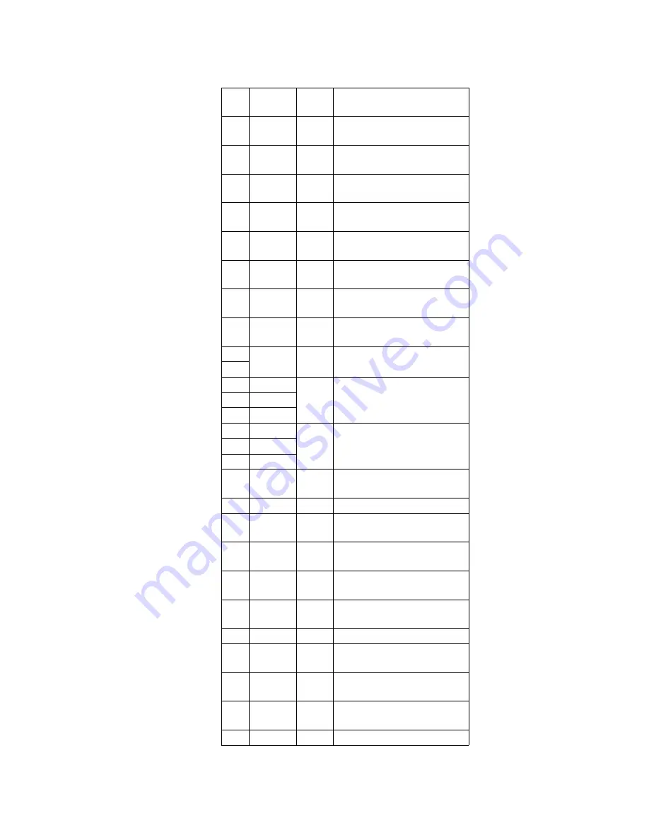
Pin
No.
Mark
I/O
Division
Function
34
OPEN
SW
I
Cover open/close detect
terminal (“H”:open)
35
PLAY
KEY
I
Play key input terminal (“L”
:STOP/PLAY)
36
AGC TC
O
RF AGC select output
terminal (Not used, open)
37
PC
O
Driver IC stand by output
terminal
38
ZDTCL
I
Lch no signal detect input
terminal (“H”:no signal)
39
FOK
I
Focus OK signal input
terminal
40
ZDTCR
I
Rch no signal detect input
terminal (“H”:no signal)
41
RESETB
O
System reset output
terminal
42
—
—
Not used, open
43
44
UO
O
Stepping motor control
output terminal
45
VO
46
WO
47
UI
I
Stepping motor control
input terminal
48
VI
49
WI
50
LDON
O
Laser on output terminal
(“L”:laser ON)
51
—
—
Not used, open
52 EEPDATA0 O
EEP ROM data output
terminal
53
EEPCK
O
EEP ROM clock output
terminal
54
EEPCS
O
EEP ROM chip select
output terminal
55 EEPDATAI
I
EEP ROM data input
terminal
56
—
—
Not used, open
57
HOLD
I
Hold switch input terminal
(“L”:Hold switch off)
58
MUTEA
O
Analog mute A output
terminal
59
MUTEB
O
Analog mute B output
terminal
60
—
—
Not used, open
56
Summary of Contents for SJ-MJ75
Page 9: ...9 ...
Page 10: ... Check the P C B A side as shown below 5 1 2 Checking for the P C B B side 10 ...
Page 11: ... To check the IC501 on side B of P C B refer to the table 1 and illustration below 11 ...
Page 12: ...12 ...
Page 13: ...5 2 Replacement for the intermediate cabinet Follow the Step 1 Step 3 of item 5 1 1 13 ...
Page 14: ...14 ...
Page 15: ...15 ...
Page 16: ...16 ...
Page 17: ...17 ...
Page 18: ...18 ...
Page 20: ...20 ...
Page 21: ...5 4 Replacement for the traverse motor Follow the Step 1 Step 3 of item 5 1 1 21 ...
Page 22: ...22 ...
Page 23: ...23 ...
Page 24: ...24 ...
Page 26: ...26 ...
Page 27: ...27 ...
Page 28: ...28 ...
Page 29: ...29 ...
Page 36: ...36 ...
Page 37: ...37 ...
Page 38: ...38 ...
Page 39: ...39 ...
Page 40: ...40 ...
Page 41: ...41 ...
Page 42: ...42 ...
Page 43: ...43 ...
Page 44: ...44 ...


