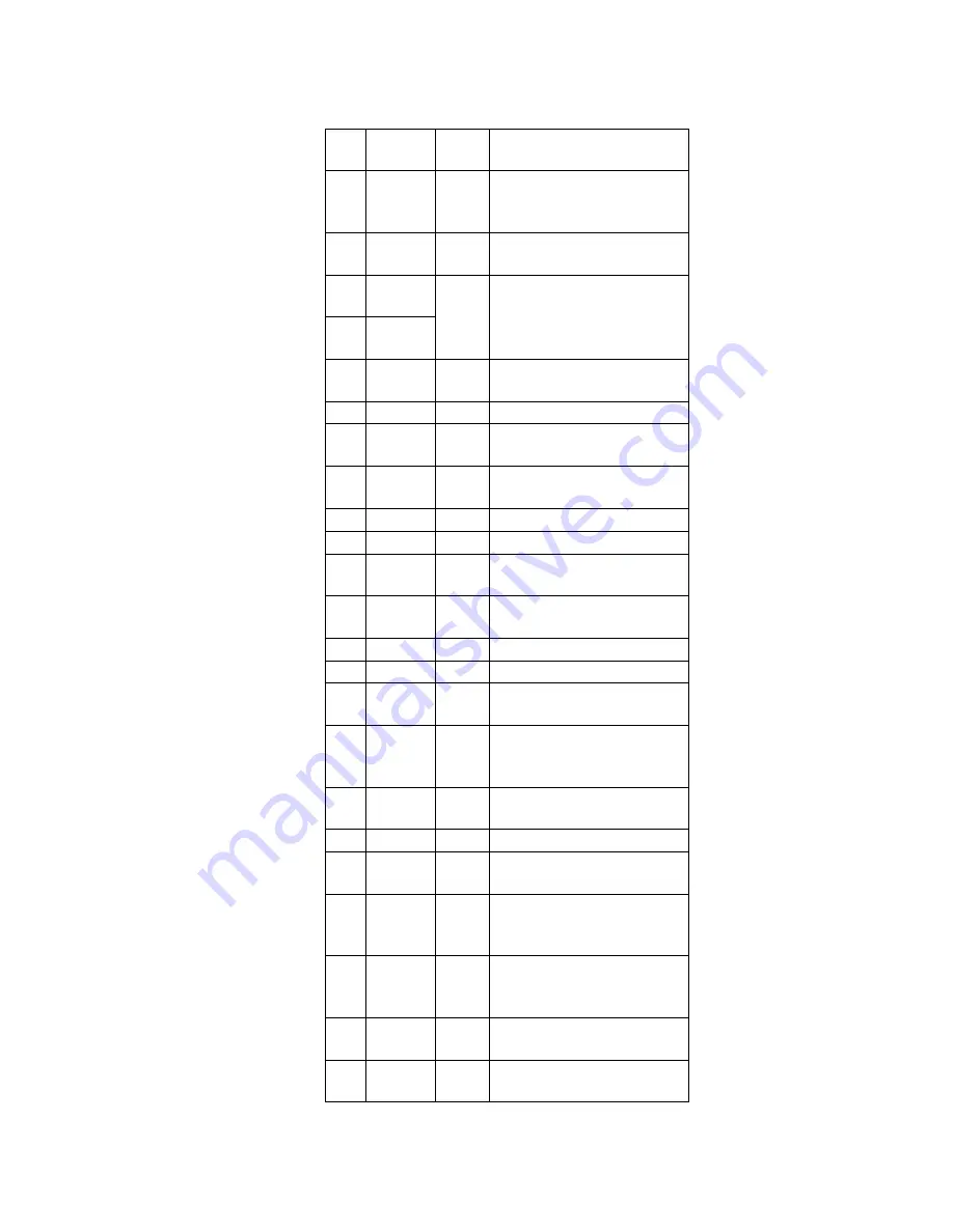
Pin
No.
Mark
I/O
Division
Function
50
MAD0
O
Adress output terminal to
DRAM
(Not used, open)
51
FOP
WMR
O
Focus PWM output terminal
52
TRP
WMF
O
Tracking PWM output
terminal
53
TRP
WMR
54
TESTI0
—
Input terminal for test
(Not used, open)
55
AVDD
I
Power supply terminal
56
OUTL
O
1 bit DAC L channel output
terminal
57
OUTR
O
1 bit DAC R channel output
terminal
58
AVSS
—
GND terminal
59
VDD2
I
Power supply terminal
60
X IN
I
Crystal oscillator input
teminal (f=16.9344MHz)
61
X OUT
O
Crystal oscillator output
teminal (f=16.9344MHz)
62
VSS
—
GND terminal
63
VDD1
I
Powe supply terminal
64
F16M
O
16.9344MHz output terminal
(Not used, open)
65
ENH
O
De-emphasis output
terminal
(Not used, open)
66
LRCO
O
LR clock output terminal
(Not used, open)
67
DDATA
O
Not used, open
68
BCO
O
Bit clock output terminal
(Not used, open)
69
DDOUT
O
Digital audio output
terminal
(Not used, open)
70
SMON3
O
Monitor signal output
terminal
(Not used, open)
71
SMON2
O
Monitor signal 2 output
terminal
72
SMON1
O
Monitor signal 1 output
terminal
52
Summary of Contents for SJ-MJ75
Page 9: ...9 ...
Page 10: ... Check the P C B A side as shown below 5 1 2 Checking for the P C B B side 10 ...
Page 11: ... To check the IC501 on side B of P C B refer to the table 1 and illustration below 11 ...
Page 12: ...12 ...
Page 13: ...5 2 Replacement for the intermediate cabinet Follow the Step 1 Step 3 of item 5 1 1 13 ...
Page 14: ...14 ...
Page 15: ...15 ...
Page 16: ...16 ...
Page 17: ...17 ...
Page 18: ...18 ...
Page 20: ...20 ...
Page 21: ...5 4 Replacement for the traverse motor Follow the Step 1 Step 3 of item 5 1 1 21 ...
Page 22: ...22 ...
Page 23: ...23 ...
Page 24: ...24 ...
Page 26: ...26 ...
Page 27: ...27 ...
Page 28: ...28 ...
Page 29: ...29 ...
Page 36: ...36 ...
Page 37: ...37 ...
Page 38: ...38 ...
Page 39: ...39 ...
Page 40: ...40 ...
Page 41: ...41 ...
Page 42: ...42 ...
Page 43: ...43 ...
Page 44: ...44 ...


