Do not touch the legs of IC or LSI with the fingers directly.
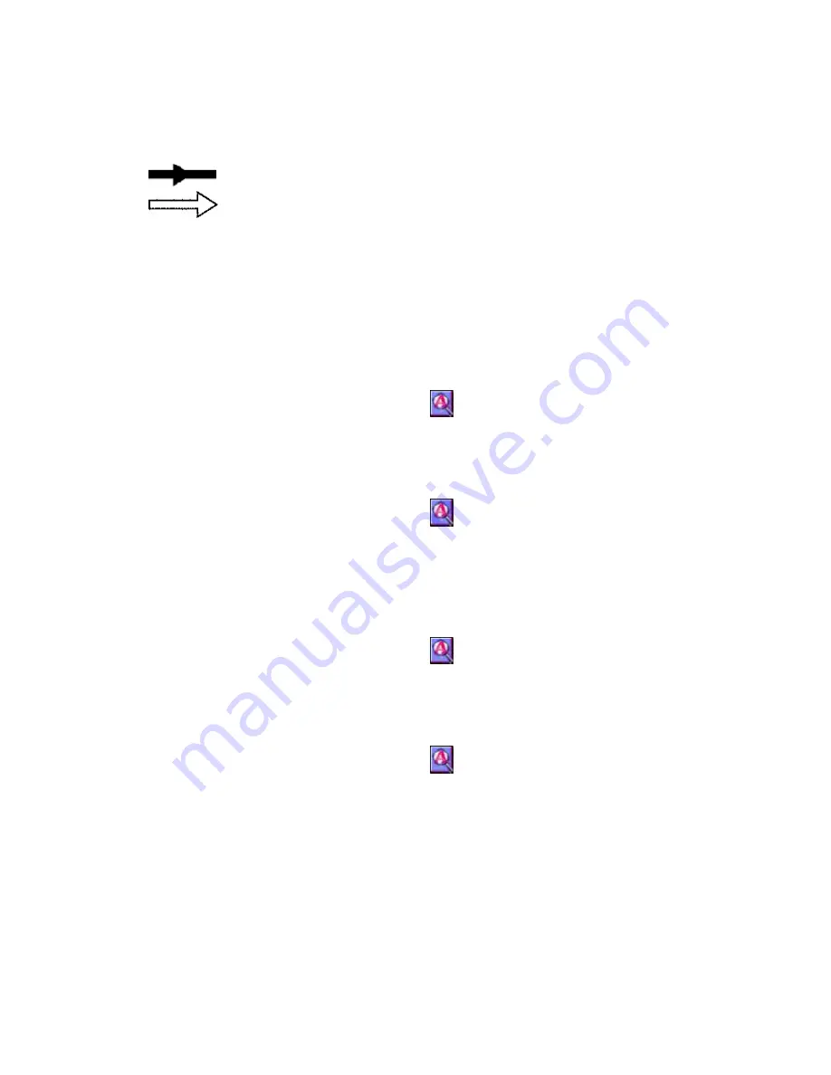
Voltage and signal line
: Positive voltage line
: Playback signal line
8.2. Type Illustration of IC's, Transistors and Diodes
9. Schematic Diagram
10. Printed Circuit Board and Wiring Connection
Diagram
11. Block Diagram
12. Terminal Function of IC 's
12.1. IC1 (LA9607T-TFM) : RF AMP
46
Summary of Contents for SJ-MJ75
Page 9: ...9 ...
Page 10: ... Check the P C B A side as shown below 5 1 2 Checking for the P C B B side 10 ...
Page 11: ... To check the IC501 on side B of P C B refer to the table 1 and illustration below 11 ...
Page 12: ...12 ...
Page 13: ...5 2 Replacement for the intermediate cabinet Follow the Step 1 Step 3 of item 5 1 1 13 ...
Page 14: ...14 ...
Page 15: ...15 ...
Page 16: ...16 ...
Page 17: ...17 ...
Page 18: ...18 ...
Page 20: ...20 ...
Page 21: ...5 4 Replacement for the traverse motor Follow the Step 1 Step 3 of item 5 1 1 21 ...
Page 22: ...22 ...
Page 23: ...23 ...
Page 24: ...24 ...
Page 26: ...26 ...
Page 27: ...27 ...
Page 28: ...28 ...
Page 29: ...29 ...
Page 36: ...36 ...
Page 37: ...37 ...
Page 38: ...38 ...
Page 39: ...39 ...
Page 40: ...40 ...
Page 41: ...41 ...
Page 42: ...42 ...
Page 43: ...43 ...
Page 44: ...44 ...


