51
© Panasonic Industrial Devices SUNX Co., Ltd. 2012 MJEC-SF4B01V2 No.0027-44V
English
7. Beam-axis Alignment
1. Turn ON the power supply unit of this device.
2. Check that the digital error indicator (red) and the fault indicator (yellow) of the emitter
and receiver are OFF respectively.
If the digital error indicator (red) or the fault indicator (yellow) lights up or blinks, refer to
“
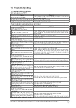
11. Troubleshooting
,” and report the symptoms to the maintenance in charge.
3. In case of using the intermediate supporting bracket
MS-SFB-2
, loosen the two hexagon-socket head bolt
(M5).
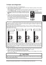
4. Loosen the hexagon-socket head bolt for beam axis
alignment of the mounting bracket, and adjust the emit-
ter / receiver so that the beam-axis alignment indicators
in the display of the emitter and receiver light up.
>] [ =
15 degrees.
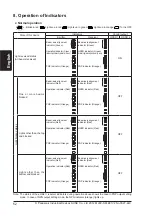
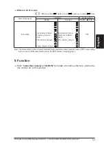
The beam-axis alignment indicator indicates the reception status for each section of the device which is
divided into 4 sections. Furthermore, the A (D) of the beam-axis alignment indicates the light-receiving
status of the device top end (bottom end).
For example, when using a 24-beam channel device, there are 6 beam channels per section (i.e.,
24/4=6). When the top end (bottom end) beam channel is received, the A (D) of the beam-axis align-
ment indicator blinks in red.
(Example) 24 beam channels
When all the 6 beam channels divided into each section are received, the beam-axis alignment indica-
tor lights up in red. The indicators corresponding to the different sections light up in red, one by one,
when the beam channels of the respective sections are received. When all the beam channels are re-
ceived and the control output (OSSD 1 / 2) turns ON, all the four indicators of the beam-axis alignment
indicator turn into green.
5. After the adjustment, tighten the hexagon-socket head bolt for beam-axis alignment of
the mounting bracket. The tightening torque should be 2N·m or less.
6. Tighten the two intermediate supporting brackets (M5).
Check, once again, that the beam-axis alignment indicators in the display of the emitter
and receiver do light up.
CAUTION
] j]}] ] j-
=_
<Reference>
Hexagon-socket head bolt
for beam-axis alignment
15°
15°
5 beam channels exclud-
ing the top end beam
channel are received
Beam-axis align-
ment indicator
All: Turns OFF
Beam-axis align-
ment indicator
A: Blinks
B to D: Turns OFF
5 beam channels includ-
ing the top end beam
channel are received
Light received
Light blocked
Beam-axis align-
ment indicator
A: Blinks
B to D: Turns OFF
Only top end beam
channel is received
6 beam channels
in top section are
received
Beam-axis align-
ment indicator
A: Lights up
B to D: Turns OFF

