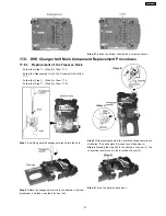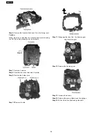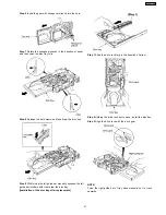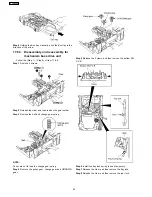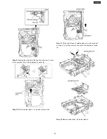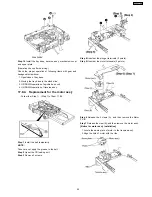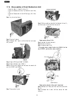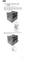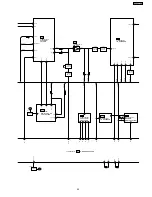
Step 1
Release the 2 claws, and then remove the head
connector.
Step 2
Remove 6 screws.
Step 3
Remove the sub chassis.
Step 4
Remove 2 screws.
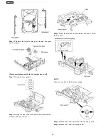
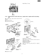
Step 14
Remove 2 screws.
Step 5
Remove the flywheel R.
Step 6
Release the claw of tape side, and then remove the
winding lever and spring.
Step 7
Remove the flywheel F.
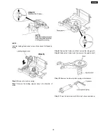
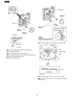
[Installation of the belt]
Step
1
The
boss
and
marking
should
be
positioned
horizontally.
17.9.1. Replacement for the CD motor ass’y, capstan belt A, capstan belt B and winding
belt
51
SA-VK61DGS
Summary of Contents for SB-VK61
Page 10: ...10 Operation Procedures 10 SA VK61DGS ...
Page 11: ...11 SA VK61DGS ...
Page 12: ...11 Disc information 12 SA VK61DGS ...
Page 13: ...13 SA VK61DGS ...
Page 17: ...13 Procedure for repairing the set 17 SA VK61DGS ...
Page 57: ...18 3 1 Cassette Deck Section 18 3 2 Adjustment Point 18 3 Alignment Points 57 SA VK61DGS ...
Page 131: ...25 1 Deck Mechanism RAA3412 S 25 1 1 Deck Mechanism Parts Location 131 SA VK61DGS ...
Page 132: ...132 SA VK61DGS ...
Page 135: ...135 SA VK61DGS ...
Page 136: ...136 SA VK61DGS ...
Page 138: ...25 3 Cabinet 25 3 1 Cabinet Parts Location 138 SA VK61DGS ...
Page 139: ...139 SA VK61DGS ...
Page 140: ...140 SA VK61DGS ...
Page 155: ...25 6 Packaging 155 SA VK61DGS PRT0406 D K J N L ...
Page 156: ......

