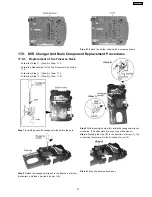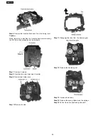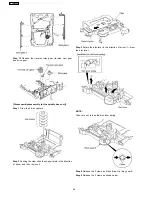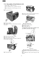
Step 1
Remove the 4 screws.
Step 2
Detach wire.
NOTE:
Insulate Power P.C.B. with insulation material to avoid short
circuit.
·
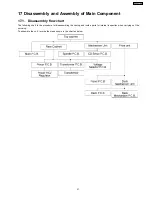
Disassembly of the Transformer P.C.B. & Voltage
Selector P.C.B.
−
−
−
−
Follow the (Step 1) - (Step 2) of Item 17.2.
−
−
−
−
Follow the Disassembly for the Top Ornament Unit of
Item 17.4.
−
−
−
−
Follow the (Step 1) - (Step 4) of Item 17.5.
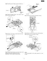
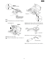
Step 1
Remove 4 screws.
Step 2
Disconnect connector CN950 & CN951.
·
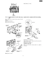
Replacement of Power Amp IC
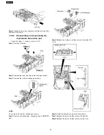
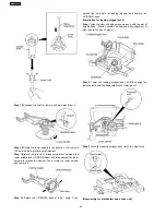
Step 1
Remove the 2 screws fixed to the Power Amplifier IC.
Step 2
Remove 2 screws fixed to the Power Amplifier IC and
Transistor Holders.
Step 3
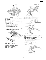
Break the joint with a metal cutter as shown below.
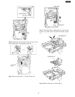
Step 4
Unsolder the terminals of Power Amp IC, replace the
component.
36
SA-VK61DGS
Summary of Contents for SB-VK61
Page 10: ...10 Operation Procedures 10 SA VK61DGS ...
Page 11: ...11 SA VK61DGS ...
Page 12: ...11 Disc information 12 SA VK61DGS ...
Page 13: ...13 SA VK61DGS ...
Page 17: ...13 Procedure for repairing the set 17 SA VK61DGS ...
Page 57: ...18 3 1 Cassette Deck Section 18 3 2 Adjustment Point 18 3 Alignment Points 57 SA VK61DGS ...
Page 131: ...25 1 Deck Mechanism RAA3412 S 25 1 1 Deck Mechanism Parts Location 131 SA VK61DGS ...
Page 132: ...132 SA VK61DGS ...
Page 135: ...135 SA VK61DGS ...
Page 136: ...136 SA VK61DGS ...
Page 138: ...25 3 Cabinet 25 3 1 Cabinet Parts Location 138 SA VK61DGS ...
Page 139: ...139 SA VK61DGS ...
Page 140: ...140 SA VK61DGS ...
Page 155: ...25 6 Packaging 155 SA VK61DGS PRT0406 D K J N L ...
Page 156: ......


