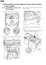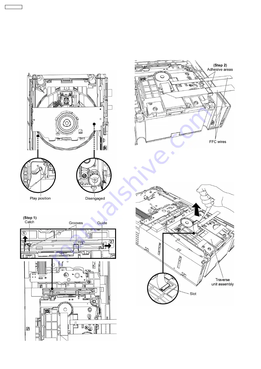
10.1. Disassembly of Traverse Unit
(TRV) Assembly
•
•
•
•
Disassembly of TRV unit assembly in play position.
•
•
•
•
Note: The above picture shows the units is in play position.
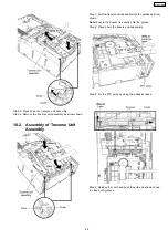
Step 1: Release the catch and push the guide as arrows shown
to open both grooves.
Step 2: Detach the FFC wires from the adhesive areas.
Caution:
Do not pull the FFC wire to remove the traverse unit
assembly, as it may cause damage to the slot.
10 Disassembling and assembling Traverse Unit Assembly
in play position
68
SA-VK470EE
Summary of Contents for SA-VK470EE
Page 3: ...3 SA VK470EE ...
Page 12: ...12 SA VK470EE ...
Page 40: ...40 SA VK470EE ...
Page 42: ...9 3 Main Components and P C B Location 42 SA VK470EE ...
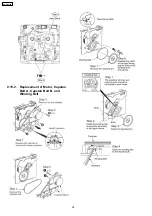
Page 54: ...9 15 2 Replacement of Motor Capstan Belt A Capstan Belt B and Winding Belt 54 SA VK470EE ...
Page 88: ...SA VK470EE 88 ...
Page 98: ...98 SA VK470EE ...
Page 116: ...SA VK470EE 116 ...
Page 124: ...SA VK470EE 124 ...
Page 136: ...136 SA VK470EE ...
Page 137: ...24 Exploded Views 24 1 Cabinet Parts Location SA VK470EE 137 ...
Page 138: ...SA VK470EE 138 ...
Page 139: ...24 2 Deck Mechanism Parts Location RAA4111 S SA VK470EE 139 ...
Page 140: ...24 3 Packaging SA VK470EE 140 ...

