9.1. Caution
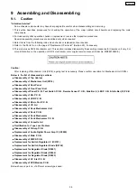
Below is the list of disassembly sections
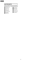
Below shown is part no. of different screws types used:
9 Assembling and Disassembling
“Attention Servicer”
Some chassis components may have sharp edges. Be careful when disassembling and servicing.
1. This section describes procedures for checking the operation of the major printed circuit boards and replacing the main
components.
2. For reassembly after operation checks or replacement, reverse the respective procedures.
Special reassembly procedures are described only when required.
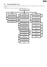
3. Select items from the following index when checks or replacement are required.
4. Refer to the Parts No. on the page of “Replacement Parts List” (Section 25), if necessary.
5. This model uses CR14 Mechanism unit. This section includes disassembly & assembly procedures for traverse unit only. For
more information on the operation of CR14 mechanism, refer original service manual (Order No. MD0801004CE).
Caution:
After replacing of Mechanism Unit (CR14), ageing test is necessary. Please confirm operation for Mechanism Unit (CR14).
•
•
•
•
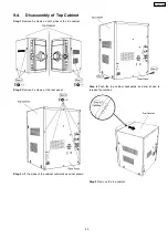
Disassembly of Top Cabinet
•
•
•
•
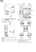
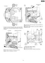
Disassembly of Mechanism Unit (CR14)
•
•
•
•
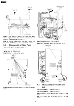
Disassembly of Rear Panel
•
•
•
•
Disassembly of Front Panel Unit
•
•
•
•
Disassembly of Panel P.C.B., Tact Switch P.C.B., Remote Sensor P.C.B., Side Bar (L) LED P.C.B. & Side Bar (R) P.C.B.
•
•
•
•
Disassembly of Mic P.C.B.
•
•
•
•
Disassembly of USB P.C.B.
•
•
•
•
Disassembly of Music Port P.C.B.
•
•
•
•
Disassembly of CD Lid
•
•
•
•
Disassembly of Deck Mechanism Unit
•
•
•
•
Disassembly of Deck P.C.B.
•
•
•
•
Disassembly of Deck Mechanism
•
•
•
•
Disassembly of Deck Mechanism P.C.B.
•
•
•
•
Disassembly of Cassette Lid
•
•
•
•
Rectification for Tape Jam Problem
•
•
•
•
Disassembly of D-Amp P.C.B.
•
•
•
•
Replacement of Audio Digital Power Amp IC (IC5000)
•
•
•
•
Disassembly of Main P.C.B.
•
•
•
•
Disassembly of SMPS P.C.B.
•
•
•
•
Replacement for Switch Regulator IC (IC5701)
•
•
•
•
Replacement for Switch Regulator Diode (D5702)
•
•
•
•
Replacement for Regulator Diode (D5801)
•
•
•
•
Replacement for Regulator Diode (D5802)
•
•
•
•
Replacement for Regulator Diode (D5803)
•
•
•
•
Disassembly of AC Inlet P.C.B.
•
•
•
•
Disassembly of DVD Module P.C.B.
39
SA-VK470EE
Summary of Contents for SA-VK470EE
Page 3: ...3 SA VK470EE ...
Page 12: ...12 SA VK470EE ...
Page 40: ...40 SA VK470EE ...
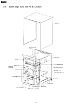
Page 42: ...9 3 Main Components and P C B Location 42 SA VK470EE ...
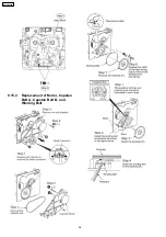
Page 54: ...9 15 2 Replacement of Motor Capstan Belt A Capstan Belt B and Winding Belt 54 SA VK470EE ...
Page 88: ...SA VK470EE 88 ...
Page 98: ...98 SA VK470EE ...
Page 116: ...SA VK470EE 116 ...
Page 124: ...SA VK470EE 124 ...
Page 136: ...136 SA VK470EE ...
Page 137: ...24 Exploded Views 24 1 Cabinet Parts Location SA VK470EE 137 ...
Page 138: ...SA VK470EE 138 ...
Page 139: ...24 2 Deck Mechanism Parts Location RAA4111 S SA VK470EE 139 ...
Page 140: ...24 3 Packaging SA VK470EE 140 ...


