


No.
Operation Procedures
Micon operation & processing
3
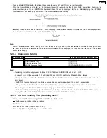
[
] key is pressed, after loading a NORMAL,
CrO2, METAL type cassette with the recording
tab on the right side removed.
REW shall be executed for 2 sec, afterwhich STOP.
Check the following.
{ F.REC INH SW } is ON
{ HALF SW } is ON
Reel pulse toggles between H & L.
4
[TAPE
] Key is pressed, after loading in a
NORMAL, CrO2, METAL type cassette (
cassette for TPS checking purposes and with
both recording tabs intact ).
TPS operation is executed. Check the following.
{ F.REC INH SW } is ON
{ HALF SW } is ON
TPS signal changes.
After checking TPS, it shall STOP.
If TPS checking is completed at TAPE END, it is considered as TPS
abnormal.
5
[REC] key is pressed, after loading in a
NORMAL type cassette ( with both recording
tabs intact )
REC operation shall not be executed.
Check the following.
{ F.REC INH SW } is ON
{ HALF SW } is ON
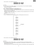
6
Self-diagnostic mode is stopped by pressing
the [STOP
n
] Key.
LCD shall display the abnormality item code, when the STOP key is pressed,
it shall display the abnormality item code in the following sequence.
[ TEST H 0 1 ] [ TEST H 0 2 ] [ TEST H 0 3 ]
7
To clear all the abnormalities in the memory,
press the [STOP
n
] Key for more than 5 Sec
while the self-diagnostic mode is stopped.
At this time, all the abnormalities item in the memory is cleared and is
displayed on the LCD.[ C L E A R ] display for 1 Sec. then,[ TEST ] is
displayed.
8
To cancel the self-diagnostic mode press the
[POWER] Key.
POWER is OFF.At the next POWER ON, normal operation shall be executed.
·
As HALF SW solder point and RECINH SW solder point are located close to each other, it’s necessary to check the shorting
between the adjacent points. For this purpose, operation has to be executed twice using two kind of cassettes, i.e. a cassette
with recording preventive tabs for both Sides A/B and a cassette with a recording preventive tab for only either one side of Side
A/B.
12.1.5. Error Code for CD Mechanism
Error code
Possible symptom
Possible cause
H01
DECK operation
abnormal (reel motor,
solenoid, and MODE
SW)
·
During normal operation, if mechanism error process is executed once by mode switch against the
same deck operation, it is judged as mechanism abnormality and this is memorized as an error.
·
Conditions for judging mechanism error:
−
Mode switch ON is not detected 800 ms after plunger activation for PLAY / REC process.
−
Mode switch ON is not detected 800 ms after plunger activation for FF / REW process. Or, Mode
switch OFF is not detected 800 ms after plunger activation after detecting Mode SW ON. Or,
Mode Switch ON is not detected 800 ms after detecting Mode switch OFF.
−
If Mode switch comes ON at STOP / PAUSE state (normal condition), this is judged as an Error:
1.
Main purpose for this Self Diagnosis is to diagnose a partial short of the deck.
2.
Mechanical error process caused by EJECT operation will not be counted.
3.
This error number can be cleared only at the start up of micro-p reset.
F15
CD REST_SW
abnormal
·
At initial setting of CD traverse position, if REST SW ON is not detected even though the fail safe
timer time is over (10 sec), this is memorized as an error and the error number can be cleared only
at the start up of micro-p after reset.
H15
CD OPEN_SW
abnormal
·
During normal operation, if CD OPEN SW ON is not detected within 4 sec, then H15 will be
memorized in memory. The error code can be cleared only at the start up of micro-p after reset.
F26
Communication
between CD servo LSI
and microp abnormal
·
At the time of switching to CD function, SENSE = H will be detected using DTMS system setting
command. If the error is memorized when SENSE = L is not detected within fail safe timer time (20
sec), [F26] will be displayed simultaneously. This display will be retained if the power is ON and at
CD function. If this error occurs, CD operation afterward cannot be executed as in the case of
[NO.DISC.].
·
This error number can be cleared only at the start up of micro-p after reset.
12.2. Clearing all error code
1. Press and hold STOP button for 5 seconds.
2. FL indicator shows “CLEAR” for 1 second and change to “TEST”.
12.3. Cancelling the Self-Diagnostic mode
1. Press the “Power” button to turn off the system. Press the “Power” button again to turn on the system.
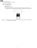
12.4. Setting of doctor mode
1. At any more (CD, TAPE, TUNER).
32
SA-PM21PC
Summary of Contents for SA-PM21PC
Page 5: ...1 1 3 Caution for fuse replacement 5 SA PM21PC ...
Page 10: ...8 Operation Procedures 10 SA PM21PC ...
Page 11: ...9 Information on CD MP3 11 SA PM21PC ...
Page 20: ...20 SA PM21PC ...
Page 21: ...21 SA PM21PC ...
Page 26: ...26 SA PM21PC ...
Page 28: ...28 SA PM21PC ...
Page 38: ...Fig 7 38 SA PM21PC ...
Page 76: ...23 Troubleshooting Flowchart CD Section Circuit 76 SA PM21PC ...
Page 77: ...77 SA PM21PC ...
Page 79: ...24 1 Deck Mechanism 24 1 1 Deck Mechanism Parts Location RAA4402 S 79 SA PM21PC ...
Page 81: ...24 2 CD Loading Mechanism 24 2 1 CD Loading Mechanism Parts Location 81 SA PM21PC ...
Page 83: ...24 3 Cabinet 24 3 1 Cabinet Parts Location 83 SA PM21PC ...
Page 84: ...84 SA PM21PC ...


