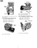


10.15. Checking Procedure for Each
Major P.C.B.
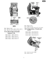
10.15.1. Replacement of the Power
Amplifier IC
·
Replacement of the Power Amplifier IC
·
Follow the (Step 1) - (Step 6) of Item 10.2.
·
Follow the (Step 1) - (Step 4) of Item 10.3.
·
Follow the (Step 1) - (Step 2) of Item 10.8.
·
Follow the (Step 1) - (Step 4) of Item 10.11.
Step 1
Remove 5 screws.
Step 2
Unsolder the terminals of Power Amp IC (IC300, IC500)
and replace the component.
Step 3
Unsolder the terminals of Transistor (Q503) and replace
the component.
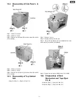
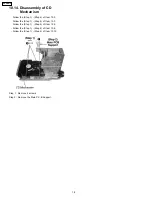
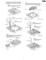
10.16. Procedures of Replacing
Traverse Base (Unit), Driving
Gear, and Cam Gear (CD
Mechanism Unit)
10.16.1. Disassembly of the Disc Tray.
·
Follow the (Step 1) - (Step 6) of Item 10.2.
·
Follow the (Step 1) - (Step 4) of Item 10.3.
·
Follow the (Step 1) - (Step 4) of Item 10.6.
·
Follow the (Step 1) - (Step 2) of Item 10.8 .
·
Follow the (Step 1) - (Step 4) of Item 10.10.
·
Follow the (Step 1) - (Step 2) of Item 10.14.
19
SA-PM21PC
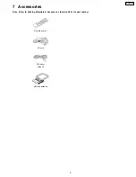
Summary of Contents for SA-PM21PC
Page 5: ...1 1 3 Caution for fuse replacement 5 SA PM21PC ...
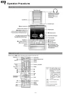
Page 10: ...8 Operation Procedures 10 SA PM21PC ...
Page 11: ...9 Information on CD MP3 11 SA PM21PC ...
Page 20: ...20 SA PM21PC ...
Page 21: ...21 SA PM21PC ...
Page 26: ...26 SA PM21PC ...
Page 28: ...28 SA PM21PC ...
Page 38: ...Fig 7 38 SA PM21PC ...
Page 76: ...23 Troubleshooting Flowchart CD Section Circuit 76 SA PM21PC ...
Page 77: ...77 SA PM21PC ...
Page 79: ...24 1 Deck Mechanism 24 1 1 Deck Mechanism Parts Location RAA4402 S 79 SA PM21PC ...
Page 81: ...24 2 CD Loading Mechanism 24 2 1 CD Loading Mechanism Parts Location 81 SA PM21PC ...
Page 83: ...24 3 Cabinet 24 3 1 Cabinet Parts Location 83 SA PM21PC ...
Page 84: ...84 SA PM21PC ...


