


10 Assembling and Disassembling
“ATTENTION SERVICER”
Some chassis components may be have sharp edges. Be careful when disassembling and servicing.
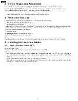
1. This section describes procedures for checking the operation of the major printed circuit boards and replacing the main
components.
2. For reassembly after operation checks or replacement, reverse the respective procedures.
Special reassembly procedures are described only when required.
3. Select items from the following index when checks or replacement are required.
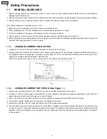
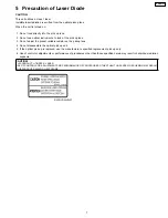
Warning:
This product uses a laser diode. Refer to “Precaution of Laser Diode”.
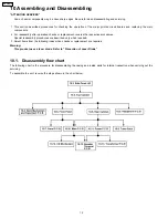
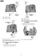
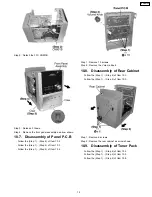
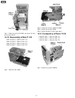
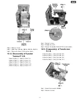
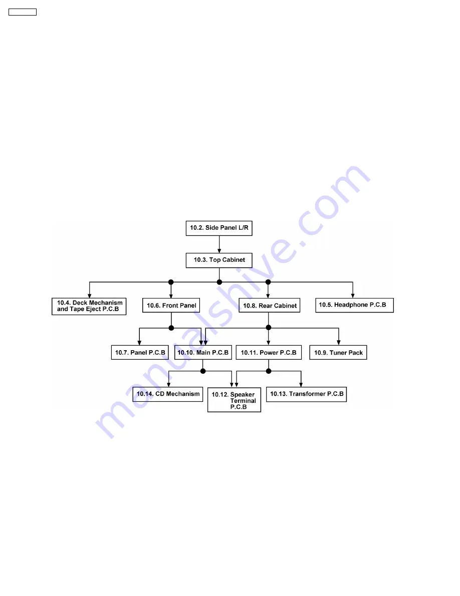
10.1. Disassembly flow chart
The following chart is the procedure for disassembling the casing and inside parts for internal inspection when carrying out the
servicing.
To assemble the unit, reverse the steps shown in the chart below.
12
SA-PM21PC
Summary of Contents for SA-PM21PC
Page 5: ...1 1 3 Caution for fuse replacement 5 SA PM21PC ...
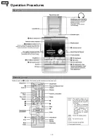
Page 10: ...8 Operation Procedures 10 SA PM21PC ...
Page 11: ...9 Information on CD MP3 11 SA PM21PC ...
Page 20: ...20 SA PM21PC ...
Page 21: ...21 SA PM21PC ...
Page 26: ...26 SA PM21PC ...
Page 28: ...28 SA PM21PC ...
Page 38: ...Fig 7 38 SA PM21PC ...
Page 76: ...23 Troubleshooting Flowchart CD Section Circuit 76 SA PM21PC ...
Page 77: ...77 SA PM21PC ...
Page 79: ...24 1 Deck Mechanism 24 1 1 Deck Mechanism Parts Location RAA4402 S 79 SA PM21PC ...
Page 81: ...24 2 CD Loading Mechanism 24 2 1 CD Loading Mechanism Parts Location 81 SA PM21PC ...
Page 83: ...24 3 Cabinet 24 3 1 Cabinet Parts Location 83 SA PM21PC ...
Page 84: ...84 SA PM21PC ...


