8.3.
Reliability Test Mode (CD Mechanism Unit (BRS1C))
Below is the process flow chart of the aging test for the CD Mechanism Unit (BRS1C).
Fig. 1. Reliability Test (Loading)
Fig. 2. Reliability Test (Traverse)
Fig. 3. Reliability Test (Combination)
OPEN
Oper
a
tion
OPEN w
a
it
for 1 s
CLOSE
Oper
a
tion
CLOSE w
a
it
for 4 s
Count up
First Tr
ac
k
A
cc
ess
First Tr
ac
k
Pl
a
y 5 s
L
a
st Tr
ac
k
A
cc
ess
L
a
st Tr
ac
k
Pl
a
y 5 s
Count up
First Tr
ac
k
A
cc
ess
A
cc
ess
Pl
a
y 10 s
Open
Oper
a
tion
Open w
a
it
for 1 s
CLOSE
Oper
a
tion
Count up
First Tr
ac
k
L
a
st Tr
ac
k
L
a
st Tr
ac
k
Pl
a
y 10 s
22
Summary of Contents for SA-AKX14LM-K
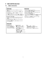
Page 14: ...5 General Introduction 5 1 Media Information 14 ...
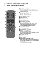
Page 15: ...6 Location of Controls and Components 6 1 Remote Control Key Button Operation 15 ...
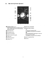
Page 16: ...6 2 Main Unit Key Button Operation 16 ...
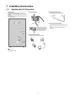
Page 17: ...7 Installation Instructions 7 1 Speaker and A C Connection 17 ...
Page 28: ... 3 D Amp IC Operation Control 28 ...
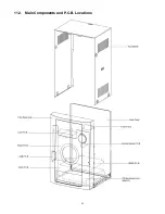
Page 33: ...11 2 Main Components and P C B Locations 33 ...
Page 63: ...Step 9 Ground the 24P FFC with a short pin 63 ...
Page 67: ...14 Simplified Block Diagram 14 1 Overall Simplified Block Diagram 67 ...
Page 68: ...14 2 Power Block Diagram 68 ...

