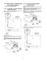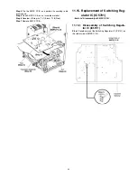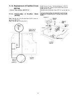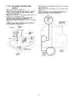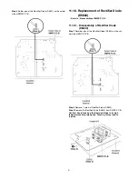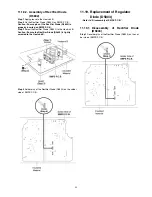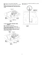
12 Replacement of Traverse Unit
12.1. Disassembly of Traverse Unit
• Refer to “Disassembly of CD Mechanism Unit (BRS1C)”.
Caution: Refer to “2.4 Handling Precaution for Traverse
Unit” to prevent static damage to the Optical Pickup Unit.
Note:
1. When the optical pickup unit is defective, the overall
traverse unit needs replacement.
2. Please note that appropriate actions need to be taken to
prevent static damage.
3. Ensure that the circuit is open before assembly BRS1 to
the main set.
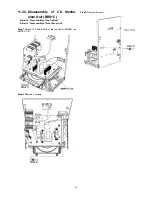
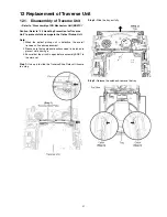
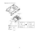
Step 1:
Use a pin to slide the Traverse Slide Plate until it come
to a stop.
Step 2:
Slide the tray out fully.
Step 3:
Release the catches & remove the tray.
57
Summary of Contents for SA-AKX14LM-K
Page 14: ...5 General Introduction 5 1 Media Information 14 ...
Page 15: ...6 Location of Controls and Components 6 1 Remote Control Key Button Operation 15 ...
Page 16: ...6 2 Main Unit Key Button Operation 16 ...
Page 17: ...7 Installation Instructions 7 1 Speaker and A C Connection 17 ...
Page 28: ... 3 D Amp IC Operation Control 28 ...
Page 33: ...11 2 Main Components and P C B Locations 33 ...
Page 63: ...Step 9 Ground the 24P FFC with a short pin 63 ...
Page 67: ...14 Simplified Block Diagram 14 1 Overall Simplified Block Diagram 67 ...
Page 68: ...14 2 Power Block Diagram 68 ...

