2-21
REEL TABLE HEIGHT ADJUSTMENT
Purpose:
To align the height of Supply and Take-Up Reel Tables
properly.
Symptom of Misadjustment:
If the height of the Reel Table is not properly aligned, the
tape will eventually be damaged.
Equipment Required:
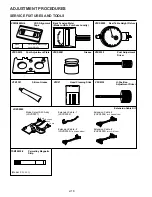
Post Adjustment Plate ............................ (VFKS0010)
Reel Table Height Fixture ....................... (VFKS0009)
Specification ................................................. 0 +/- 0.2mm
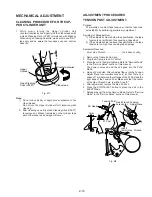
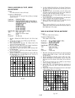
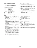
1. Remove the Cassette Up Ass'y.
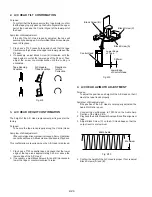
2. Position the Post Adjustment Plate over the reels.
3. Place the reel table height fixture on the Post Adjustment
Plate so that the foot of the fixture sits in the cutout portion
of the Post Adjustment Plate. Then zero the fixture.
Fig. M4-1
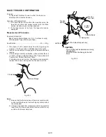
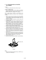
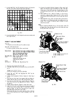
4. Measure to the top edge of each reel table. The height
should be 0 +/- 0.2 mm. If the height is not within the
specification, add or remove Reel Washers (under the reel
table) as necessary.
Fig. M4-2
Note:
Reel Washers are available in one size (0.25 mm) only.
FG HEAD GAP ADJUSTMENT
Purpose:
To properly pick up the FG Signal.
Symptom of Misadjustment:
If the FG Signal is not properly picked up, Servo Operation
cannot be achieved.
Equipment Required:
Oscilloscope
Specification .............................................. 0.13 +/- 0.02mm
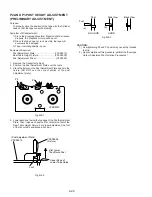
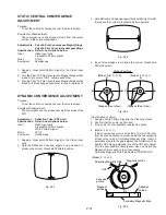
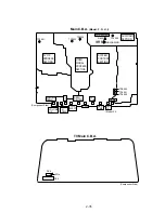
1. Remove the VCR Chassis Unit and then place it upside
down.
2. Remove the Main C.B.A.
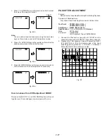
3. Slightly loosen Black Screw (A). Then set the Screwdriver
(#1 or #2 Phillips Driver) into the Hole (A). Turn the
screwdriver counterclockwise until the FG Head touches
the rotor. Then turn it slightly clockwise to the clearance as
specified.
4. Tighten Black Screw (A).
5. Reinstall the Main C.B.A.
Fig. M5
Note:
Do not touch the outside circumference of the rotor surface
with any tool and keep magnetic material away
from the rotor magnet (especially metal particles).
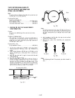
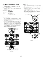
Confirmation of Signal Level
1) Supply a Video Signal to the Video Input Jack.
2) Insert a cassette tape and place the unit in SLP recording
mode.
3) Connect the oscilloscope to Pin 7 of P2502 on the Capstan
Stator Unit.
Confirm that the signal level is greater than 10mVp-p.
VFKS0009
VFKS0010
VFKS0009
VFKS0010
Reel Table
Hole (A)
FG Head
Capstan Belt
Capstan Rotor
Unit
0.13 +/- 0.02mm
Screwdriver
Black
Screw (A)
Summary of Contents for PV-M1327
Page 5: ...1 3 ...
Page 6: ...1 4 ...
Page 7: ...1 5 ...
Page 8: ...1 6 ...
Page 54: ......
Page 55: ......
Page 56: ......
Page 57: ......
Page 58: ......
Page 59: ......
Page 60: ......
Page 61: ......
Page 62: ......
Page 63: ......
Page 64: ......
Page 65: ......
Page 66: ......
Page 67: ......
Page 68: ......
Page 69: ......
Page 70: ......
Page 71: ......
Page 72: ......
Page 73: ......
Page 74: ......
Page 75: ......
Page 76: ......
Page 77: ......
Page 78: ......
Page 79: ......
Page 80: ......
Page 81: ......
Page 82: ......
Page 83: ......
Page 84: ......
Page 85: ......
Page 86: ......
Page 87: ......
Page 88: ......
Page 89: ......
Page 90: ......
Page 91: ......
Page 92: ......
Page 93: ......
Page 94: ......
Page 95: ......
Page 96: ......
Page 97: ......
Page 98: ......
Page 99: ......
Page 100: ......
Page 101: ......
Page 102: ......
Page 103: ......
Page 104: ......
Page 105: ......
Page 106: ......
Page 107: ......
Page 108: ......
Page 109: ......
Page 110: ......
Page 111: ......
Page 112: ......
Page 113: ......
Page 114: ......
Page 143: ...Printed in Japan R ...

